Propeller fan

a technology of propeller fans and blades, which is applied in the direction of liquid fuel engines, marine propulsion, and ships. it can solve the problems of reducing the efficiency of pressure efficiency, reducing the efficiency of outflow, so as to improve the power of blades, improve the efficiency of operation, and reduce the effect of heigh

Active Publication Date: 2014-03-27
SAMSUNG ELECTRONICS CO LTD
View PDF2 Cites 25 Cited by
  • Summary
  • Abstract
  • Description
  • Claims
  • Application Information

AI Technical Summary

Benefits of technology

[0041]The height of the raised portion or rib may gradually increase as the raised portion or rib extends from the leading edge of the blade toward the trailing edge. Thereby, interference between the first and second vortices may be gradually intensified, and the propulsive power of the blade may be enhanced.
[0042]The height of the raised portion or rib may gradually decrease as the raised portion or rib extends from the leading edge of the blade toward the trailing edge. Thereby, mutual interference between the first vortex and the second vortex spinning in the opposite directions may be intensified immediately after the first vortex and the second vortex are produced, and the flows may follow the paths where the first and second vortices are easily interfered with each other.
[0043]According to an air conditioner employing the propeller fan of the present invention as above, the air conditioner may be efficiently operated due to enhanced air blowing power.

Problems solved by technology

Due to the incline stream, the stream near the cylindrical hub 111A at the center of the fan is likely to become unstable, degrading the pressure efficiency.
Therefore, the conventional propeller fan may not greatly increase the pressure efficiency.
In the case that a plurality of open-cut portions is provided, vortices created between the open-cut portions may lower the speed of outflow, lowering improvement of the propulsive power of the blade.
Thereby, mutual interference between the first vortex and the second vortex spinning in the opposite directions may be intensified immediately after the first vortex and the second vortex are produced, and the flows may follow the paths where the first and second vortices are easily interfered with each other.

Method used


Image

  • Propeller fan
  • Propeller fan
  • Propeller fan

Examples


first embodiment

[0081]Hereinafter, the present invention will be described with reference to the drawings.

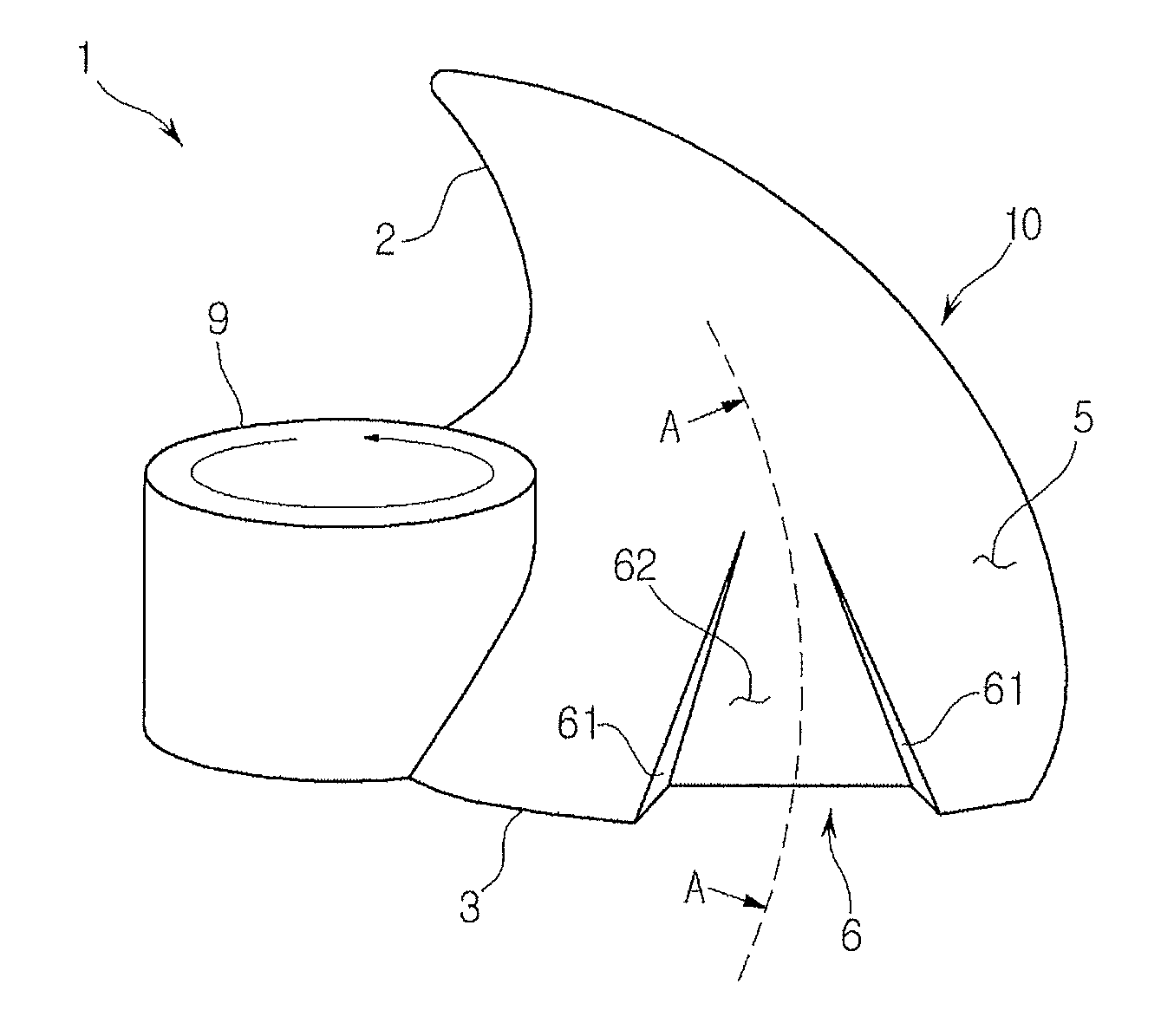
[0082]A propeller fan 1 of the first embodiment, which is applied, for example, to an outdoor of an air conditioner, includes a plurality of blades 10 radially arranged on the outer circumferential surface of a cylindrical hub 9 and spaced a predetermined distance from each other in a circumferential direction of the hub 9. In each drawing, one of the blades 10 of the propeller fan 1 is shown as a representative example.

[0083]FIG. 3 is a perspective view illustrating the shape of the blade 10 of the propeller fan 1 according to the first embodiment, seen from the side of the suction surface 5, and FIG. 4 shows a cross-section taken along line A-A of FIG. 3 in the longitudinal direction of the blade chord.

[0084]As shown in FIG. 3, the blade 10 is mounted on the lateral surface of the cylindrical hub 9 to form a predetermined spiral extending from one cross section of the hub 9 to the other cross...

second embodiment

[0097]Next, a propeller fan 1 will be described with reference to FIGS. 13 to 16.

[0098]In the second embodiment, as shown in FIG. 13, the recessed portion 6 is open not only on the pressure surface 4 but also on the suction surface 5, and thus a recessed portion 6′ is formed only by lateral portions 61′, in contrast with the first embodiment. In other words, while the first embodiment is provided with the bottom portion 62, the recessed portion 6′ of the second embodiment is provided with an opening 65′ by cutting off the bottom portion 62.

[0099]Hereinafter, a detailed description will be given of the shape of the blade 10 of the second embodiment.

[0100]As shown in FIGS. 13 and 15, the rounded triangular bottom portion 62 of the recessed portion 6′ is cut off. As illustrated in FIG. 14, showing a cross section of the recessed portion 6′ taken along line B-B of FIG. 13, and FIG. 15, showing a cross section of the recessed portion 6′ taken along line D-D of FIG. 13, the recessed port...

third embodiment

[0110]Hereinafter, a third embodiment will be described with reference to the drawings.

[0111]The propeller fan 1 according to the third embodiment, which is applied, for example, to an outdoor of an air conditioner, includes a plurality of blades 10 radially arranged on the outer circumferential surface of a cylindrical hub 9 and spaced a predetermined distance from each other in a circumferential direction of the hub 9. In each drawing, one of the blades 10 of the propeller fan 1 is shown as a representative example.

[0112]The shape of the blade 10 of the propeller fan 1 according to the third embodiment will be described with reference to FIG. 21 showing the perspective view of the blade 10 seen from the side of the suction surface 5, and FIG. 22 showing the pressure surface 4 seen along the axis of rotation of the fan X.

[0113]As shown in FIG. 21, the blade 10 is mounted on the lateral surface of the cylindrical hub 9 to form a predetermined spiral extending from one cross section ...


PUM


Abstract

A propeller fan may strongly draw the flow toward the inner circumferential side and greatly improve the pressure efficiency by degrading the tendency of the flow near the pressure surface to be inclined toward the outer circumferential side at the trailing edge of the blade. The blade is provided with a recessed portion raised toward a suction surface at a central portion of a trailing edge of the blade in a radial direction such that the recessed portion is open at least on a pressure surface of the blade, the recessed portion extending from the trailing edge toward a leading edge of the blade, and a cross section of the recessed portion taken in a radial direction is provided with a pair of lateral portions rising at a predetermined angle with respect to the suction surface and facing each other. The span-wise width of the recessed portion between the lateral portions increases as the recessed portion extends from an upstream side to a downstream side.

Description

CROSS-REFERENCE TO RELATED APPLICATIONS[0001]This application claims the benefit of Japanese Patent Application No. 2012-209744, filed on Sep. 24, 2012 in the Japanese Patent Office, Japanese Patent Application No. 2012-257610, filed on Nov. 26, 2012 in the Japanese Patent Office, and Korean Patent Application No. 2013-0091122, filed on Jul. 31, 2013 in the Korean Intellectual Property Office, the disclosures of which are incorporated herein by reference.BACKGROUND[0002]1. Field[0003]Embodiments of the present invention relate to a structure of blades of a propeller fan used for an air conditioner.[0004]2. Description of the Related Art[0005]As shown in FIG. 1, when a typical blade 110A formed in a smoothly curved shape over the entire body thereof without a projection or a recessed portion thereon rotates, the air stream near the blade pressure surface 104A is inclined toward the outer edge of the blade at the blade outlet (the blade trailing edge 103A) by centrifugal force. Due to...

Claims


Application Information

Patent Timeline
Patent Type & Authority Applications(United States)
IPC IPC(8): F04D29/32
CPCF04D29/325F04D29/384F05D2240/304
Inventor SEIJI, SATONAKAGAWA, SUGURU
Owner SAMSUNG ELECTRONICS CO LTD
Why Eureka
Try Eureka