Actuator element and an actuator for generating a force and/or a movement
- Summary
- Abstract
- Description
- Claims
- Application Information
AI Technical Summary
Benefits of technology
Problems solved by technology
Method used
Image
Examples
Embodiment Construction
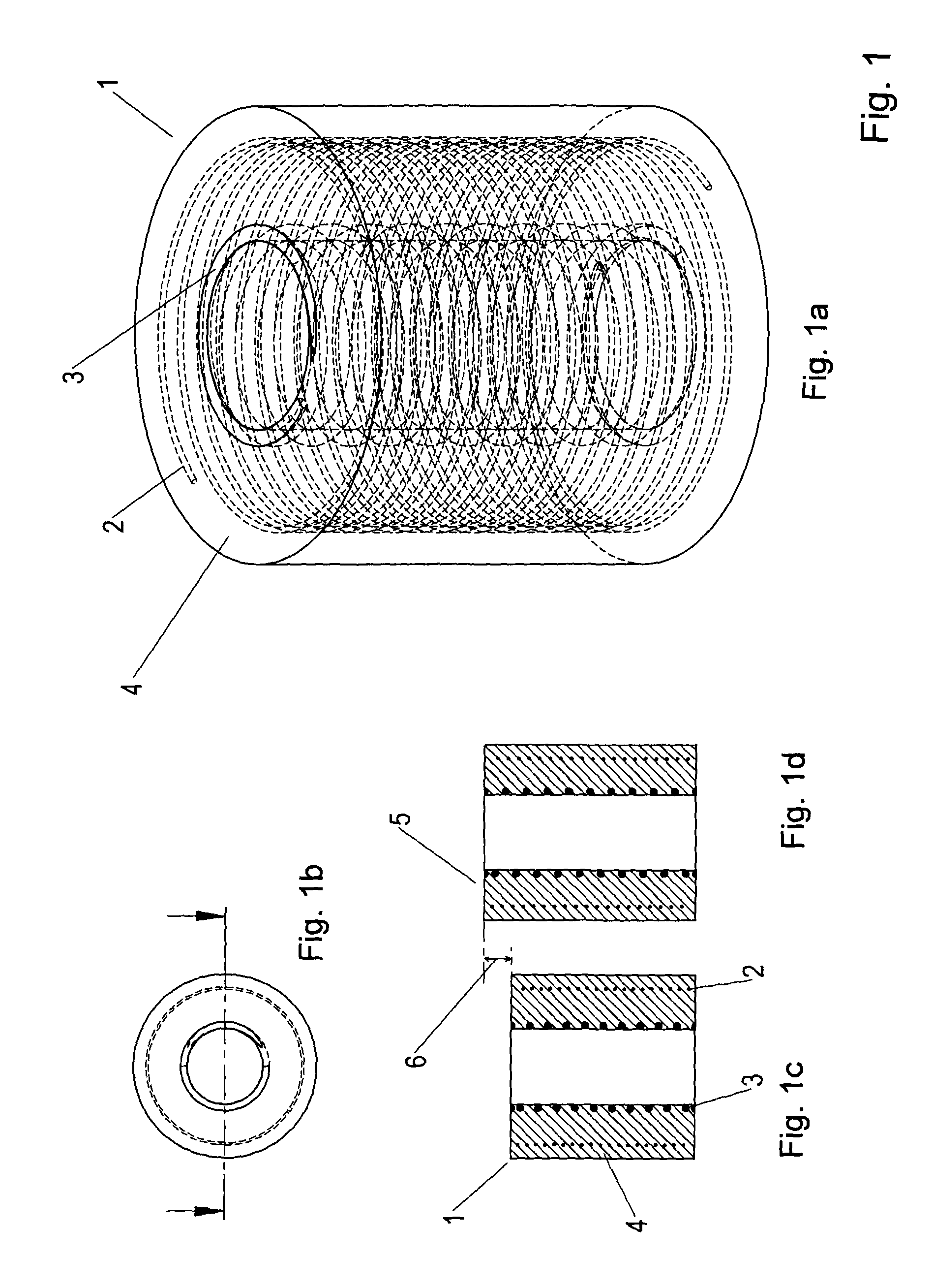
[0063]FIG. 1 shows an actuator element 1 according to the invention, comprising a tube-shaped rubber part 4 that embeds an SMA wire 2 that is wound in a helical shape and a helical spring 3. FIG. 1a shows a perspective view of the actuator element, wherein the rubber part is transparent. FIG. 1b shows a top view of the actuator element. FIG. 1c shows a cross-sectional view through the actuator element in the non-activated state. FIG. 1d is a cross-sectional view of the actuator element in the activated state. When the SMA wire 2 undergoes a phase transformation to an austenitic structure, the SMA wire 2 will contract; meaning that the diameter of the SMA windings get smaller and the tube-shaped rubber part 4 is compressed radially. This causes the actuator element 1 to go to the activated state 5 causing an expansion 6 of the length of the tube-shaped rubber part 4.
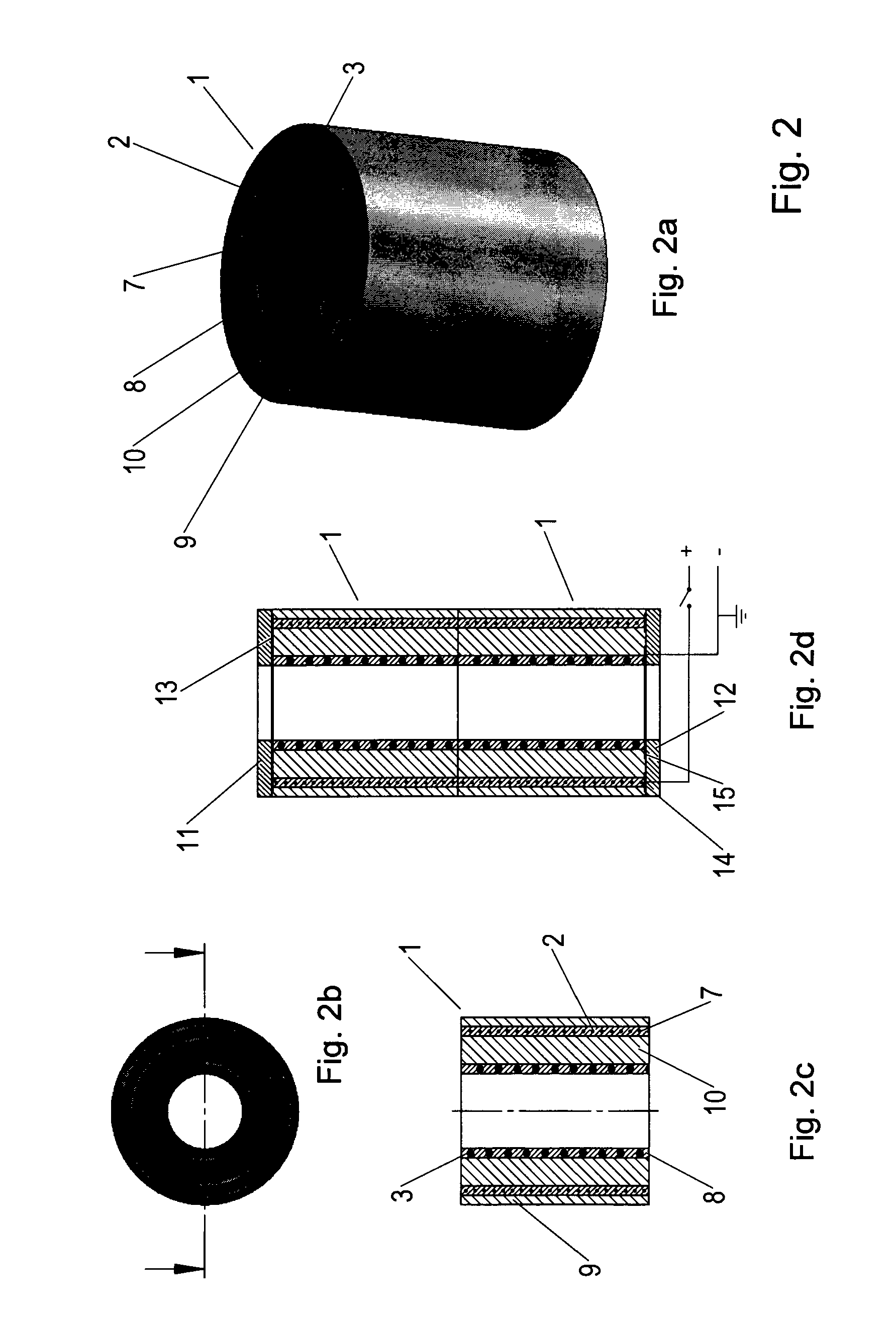
[0064]FIG. 2 shows an actuator element 1 according to the invention that comprises four tube-shaped rubber parts 7, 8, ...
PUM
 Abstract
Description
Claims
Application Information
 - R&D
- Intellectual Property
- Life Sciences
- Materials
- Tech Scout
- Unparalleled Data Quality
- Higher Quality Content
- 60% Fewer Hallucinations
Browse by: Latest US Patents, China's latest patents, Technical Efficacy Thesaurus, Application Domain, Technology Topic, Popular Technical Reports.
© 2025 PatSnap. All rights reserved.Legal|Privacy policy|Modern Slavery Act Transparency Statement|Sitemap|About US| Contact US: help@patsnap.com


