Transmitter with Improved Sensitivity and Shielding

a transmitter and shielding technology, applied in the field of magnetic field transmitters, can solve the problems of less efficient transmission coils of larger transmitters compared to smaller ones, and achieve the effect of improving the efficiency of transmission and efficient wireless communication

Active Publication Date: 2014-03-27
RED TAIL HAWK CORP
View PDF15 Cites 12 Cited by
  • Summary
  • Abstract
  • Description
  • Claims
  • Application Information

AI Technical Summary

Benefits of technology

[0007]This invention concerns magnetic field transmitters, especially transmitters that are used in conjunction with wireless communications earplugs. In one embodiment, a plate of magnetic material is used behind a coil of electrical conductor to

Problems solved by technology

However, larger transmitter coils are less efficient compared to sm

Method used


Image

  • Transmitter with Improved Sensitivity and Shielding
  • Transmitter with Improved Sensitivity and Shielding
  • Transmitter with Improved Sensitivity and Shielding

Examples


Embodiment Construction

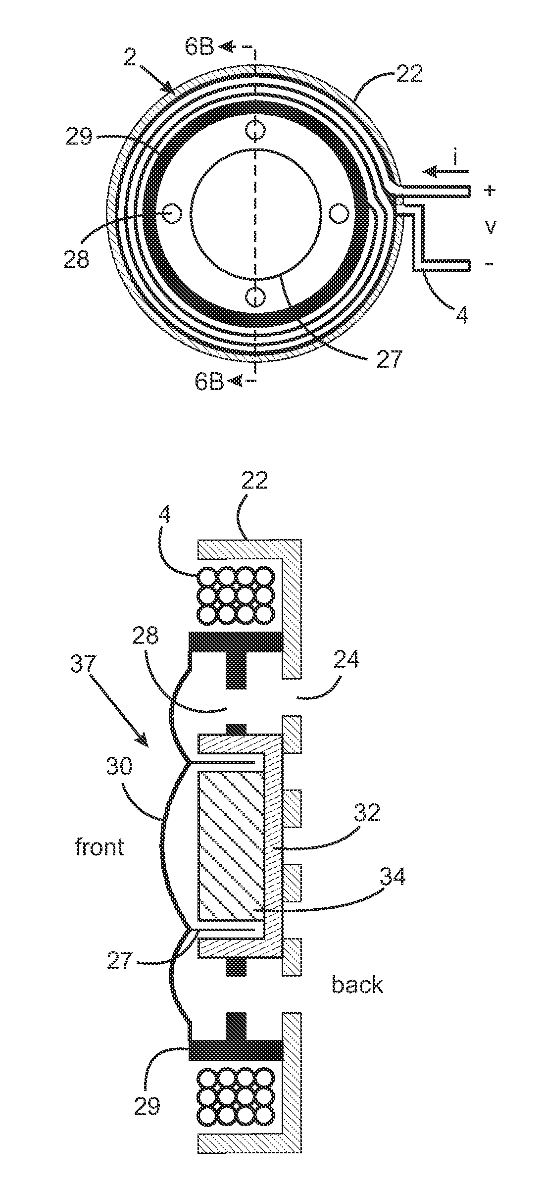
[0024]This invention concerns magnetic field transmitters, especially transmitters that are used in conjunction with wireless communications earplugs. In one embodiment, a plate of magnetic material is used behind a coil of electrical conductor to improve the efficiency of the transmitter and to provide magnetic and electrical shielding. The coil geometry of the invention improves efficiency for wireless communications with a wireless earplug.

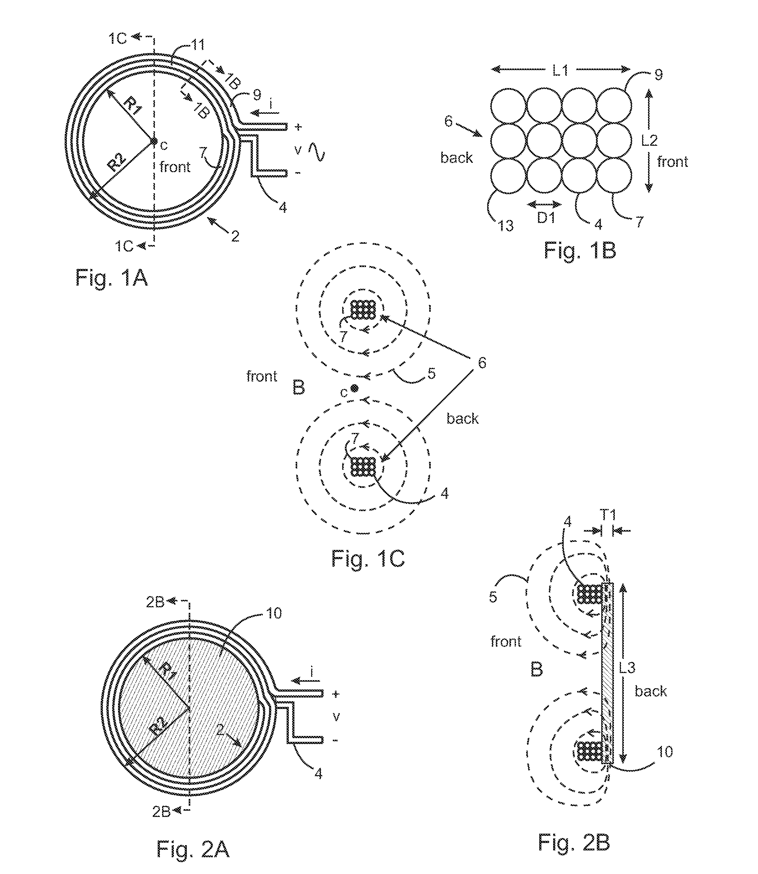
[0025]A transmitter coil 2 is shown in FIGS. 1A through 1C. The coil 2 is shown in FIG. 1A with inner radius R1 and outer radius R2 and is constructed using a continuous conductor 4 that creates loops of the coil 2. By Ohm's Law, when a voltage v is applied to the ends of the conductor 4, a current i results, and, inversely, when a current i is applied to the ends of the conductor 4, a voltage v results. The current i flows into a first loop 9, followed by a second loop 11, followed by an inner front loop 7 and continues through all loops exiti...


PUM


Abstract

A magnetic field transmitter, especially a transmitter used in conjunction with wireless communications earplugs. In one embodiment, a plate of magnetic material is used behind a coil of electrical conductor to improve the efficiency of the transmitter and to provide electrical and magnetic shielding. The specific dimensions and characteristics of the preferred embodiment of the transmitter described herein provide for efficient wireless communications.

Description

REFERENCE TO RELATED APPLICATIONS[0001]This application claims one or more inventions which were disclosed in Provisional Application No. 61 / 694,481, filed Aug. 29, 2012, entitled “Transmitter with Improved Sensitivity and Shielding”. The benefit under 35 USC §119(e) of the U.S. provisional application is hereby claimed, and the aforementioned application is hereby incorporated herein by reference.ACKNOWLEDGMENT OF GOVERNMENT SUPPORT[0002]This invention was conceived during a Navy Phase 2.5 SBIR contract N68335-09-C-0003. The government has certain rights in the invention.BACKGROUND OF THE INVENTION[0003]1. Field of the Invention[0004]This invention concerns magnetic field transmitters, especially transmitters that are used in conjunction with wireless communications earplugs.[0005]2. Description of Related Art[0006]The inventor's co-pending U.S. patent application Ser. No. 11 / 837,129, entitled “Wireless Communications Headset System Employing a Loop Transmitter that Fits Around the...

Claims


Application Information

Patent Timeline
IPC IPC(8): H04B5/00
CPCH04B5/0006H04R1/1008H04R1/1091H04R25/554H04R2209/022H04R2420/07H04B5/0075A61F11/08H01Q1/273H01Q7/06H01Q1/2291H04R1/1075
Inventor PARKINS, JOHN W.
Owner RED TAIL HAWK CORP
Why Eureka
Try Eureka