Electronic Circuit with an Electronic Switch and a Monitoring Circuit

a monitoring circuit and electronic switch technology, applied in electronic switching, relays, pulse techniques, etc., can solve the problems of electronic switch damage or even destruction, different types of failures, and increased load-path voltag

Active Publication Date: 2014-04-03
INFINEON TECH AG
View PDF4 Cites 14 Cited by
  • Summary
  • Abstract
  • Description
  • Claims
  • Application Information

AI Technical Summary

Benefits of technology

[0007]A first embodiment relates to an electronic circuit. The electronic circuit includes an electronic switch having a control terminal and a load path, a monitoring circuit including a switched-capacitor circuit with at least one capacitive storage element, the switched-capacitor network coupled to the load

Problems solved by technology

In operation of an electronic switch, different types of failures may occur, such as a short-circuit of a load connected to the switch.
At higher load currents, that is when an IGBT is operated in the desaturation region of its characteristic curve, or when a MOSFET, a JFET or a HEMT is operated in the saturation region (pinch-off region) of its characteristic curve, the load-path voltage may dramatically increase which may cause the electronic switch to be damaged or even destroyed, unless suitable measures are taken.
These solutions, however, may not be suitable to be used for

Method used


Image

  • Electronic Circuit with an Electronic Switch and a Monitoring Circuit
  • Electronic Circuit with an Electronic Switch and a Monitoring Circuit
  • Electronic Circuit with an Electronic Switch and a Monitoring Circuit

Examples


first embodiment

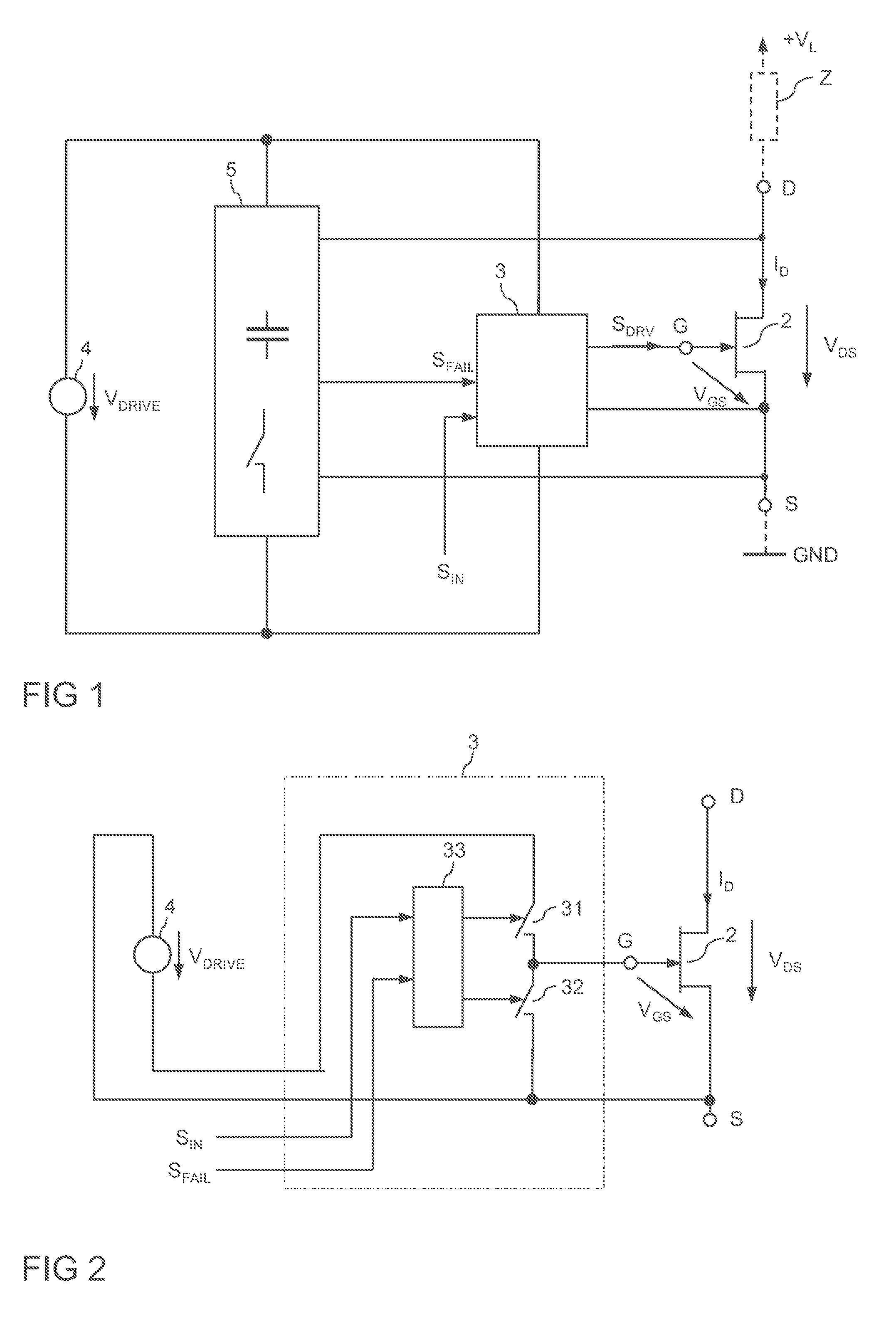
[0019]FIG. 1 illustrates an electronic circuit that includes an electronic switch 2, a drive circuit 3 for the electronic switch 2, a supply voltage source 4 and a monitoring circuit 5. In this example, the electronic switch is a normally-on device, specifically a JFET 2. However, the electronic switch is not restricted to be implemented as a normally-on device. Further, the normally-on device is not restricted to be implemented as a JFET, but could be implemented as one of a depletion MOSFET and a HEMT as well.

[0020]The electronic switch 2 has a control terminal and a load path between a first and a second load terminal. In the JFET 2 of FIG. 1, the load path is a drain-source path D-S between a drain terminal D and a source terminal S, and the control terminal is a gate terminal G. The electronic switch 2 can be used for switching an electrical load Z (illustrated in dashed lines), such as an electrical load in an automotive, industrial or consumer electronic application. In this ...

second embodiment

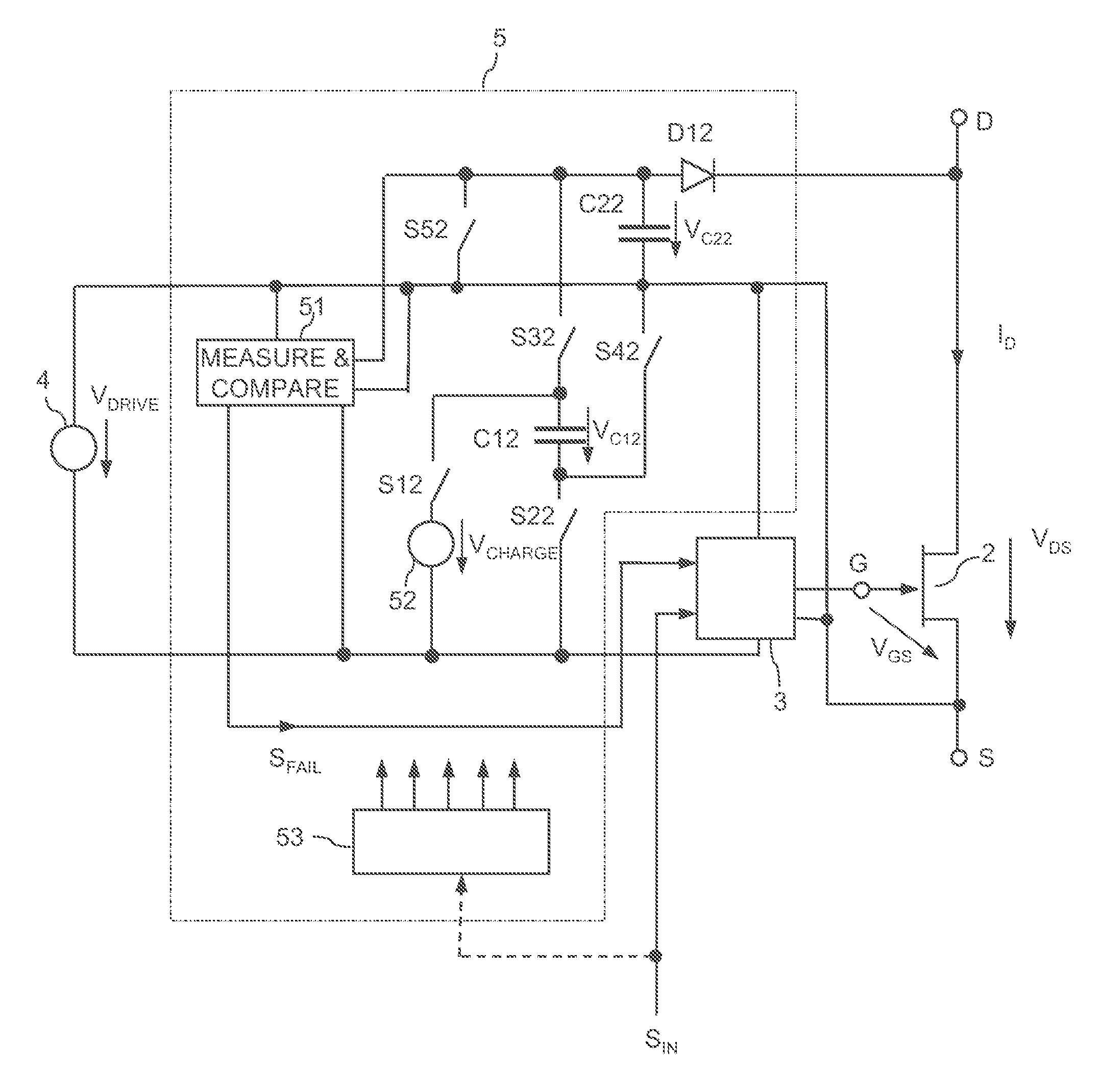
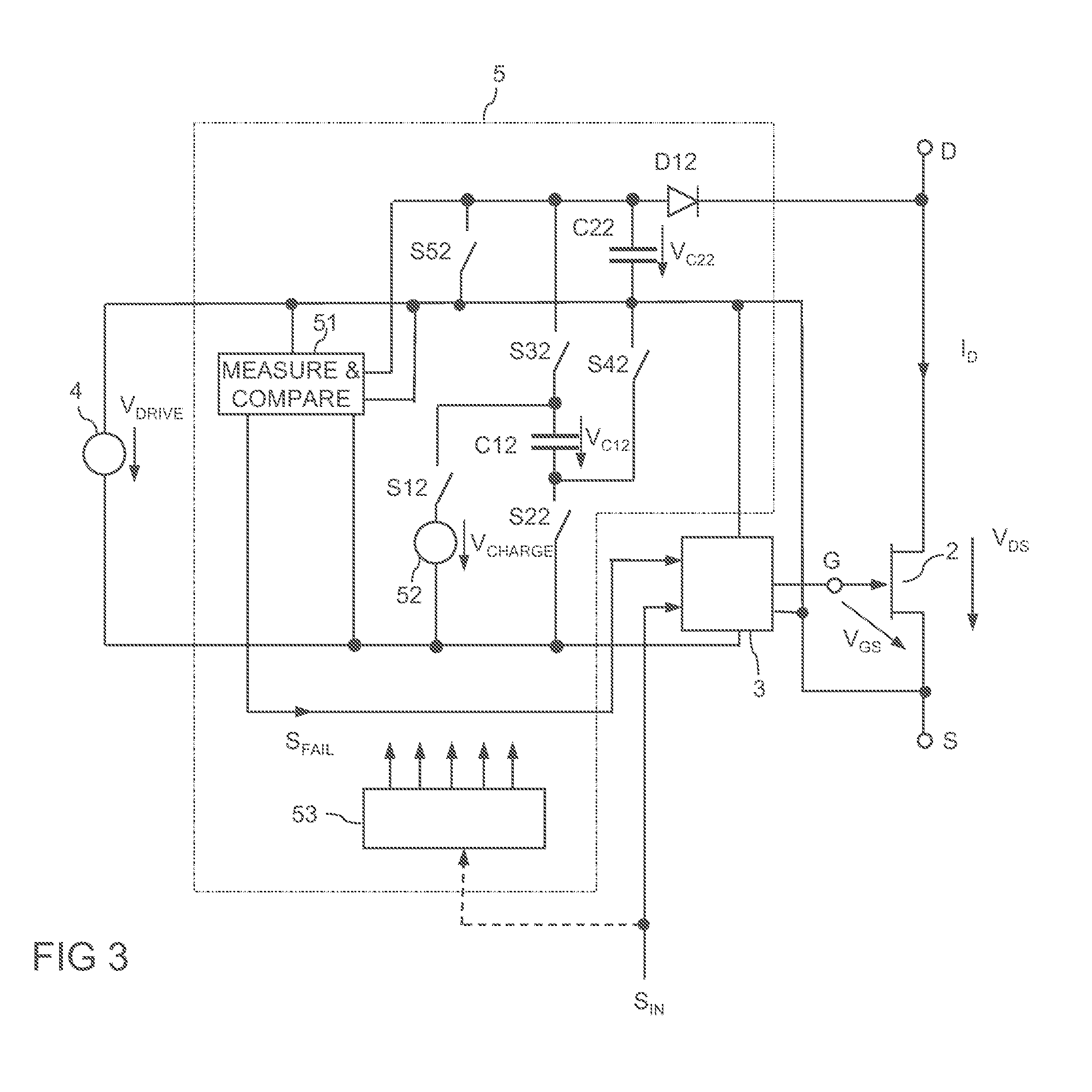
[0050]FIG. 7 illustrates a monitoring circuit 5. The monitoring circuit 5 of FIG. 7 includes several (two in the present embodiment) first capacitive storage elements C121, C122. Each of the first capacitive storage elements has a first switch network S121, S221 and S122, S222, respectively, and a second switch network S321, S421 and S322, S422, respectively, associated thereto. Each of the first and second switch networks is implemented like the first and second switch networks explained with reference to FIG. 3 herein before. The first switch network of each first capacitive storage element C121, C122 is operable to couple the corresponding first capacitive storage C121, C122 element to the charging voltage source, while the second switch network of each first capacitive storage element C121, C122 is operable to couple the corresponding first capacitive storage C121, C122 element to the second capacitive storage element.

[0051]Each of the first capacitive storage elements C121, C12...


PUM

PropertyMeasurementUnit
Electric potential / voltageaaaaaaaaaa

Abstract

An electronic circuit includes an electronic switch having a control terminal and a load path. A monitoring circuit includes a switched-capacitor circuit with a capacitive storage element. The switched-capacitor circuit is coupled to the load path of the electronic switch. The monitoring circuit is operable to evaluate a load voltage of the electronic switch and to generate a failure signal dependent on the evaluation. A drive circuit is operable to provide a drive signal at the control terminal of the electronic switch dependent on the failure signal.

Description

TECHNICAL FIELD[0001]The present disclosure relates to an electronic circuit with an electronic switch and with a monitoring circuit.BACKGROUND[0002]In many electronic circuit applications, such as power converters, semiconductor switches (also referred to as solid state switches) are used. Semiconductor switches are, e.g., MOSFETs (Metal Oxide Semiconductor Field-Effect Transistors), IGBTs (Insulated Gate Bipolar Transistors), JFETs (Junction Field-Effect Transistors), BJTs (Bipolar Junction Transistors) or HEMTs (High Electron-Mobility Transistors). In operation of an electronic switch, different types of failures may occur, such as a short-circuit of a load connected to the switch. In order to prevent the electronic switch from being damaged in case of a failure, at least one operation parameter of the electronic switch may be monitored and suitable measure may be taken, such as switching off the electronic switch, when the operation parameter indicates that a failure has occurre...

Claims


Application Information

Patent Timeline
IPC IPC(8): H02H3/00
CPCH03K17/0822H03K17/18H03K2217/0027Y10T29/49107H01H11/00H02H3/00
Inventor NORLING, KARL
Owner INFINEON TECH AG
Why Eureka
Try Eureka