
Method and system for providing an external optical data packet to a destination node of a packet optical network

data packet technology, applied in the field of providing an external optical data packet to a destination node of a packet optical network, can solve the problems of high energy consumption, no solution to efficiently interconnect different packet optical networks, and points also form bottlenecks, so as to improve the interconnection of different data optical networks, reduce energy consumption and latency of packet switching, and improve the effect of interconnection

Inactive Publication Date: 2014-04-03
NTT DOCOMO INC
View PDF3 Cites 4 Cited by
  • Summary
  • Abstract
  • Description
  • Claims
  • Application Information

AI Technical Summary

Benefits of technology

The invention provides a way to transmit optical packets between different optical networks without converting them into the electrical domain, which avoids problems of long latency, delays, and high energy consumption. The optical packets can come from an external source or another optical network and can be transferred for communication with the receiving network in a format that they can be understood. The invention also provides a method for passing a packet optically between different networks, thereby improving interconnection and reducing energy consumption and latency. Overall, the invention offers a faster, energy-efficient, and cost-effective approach for optical networking.

Problems solved by technology

Thus, while there is already a solution for optical communication within the respective networks, there is currently no solution to efficiently interconnect different packet optical networks.
This OEO conversion (OEO=Optical-Electrical-Optical) and electrical processing necessitates a lot of time and leads to a high energy consumption.
Further, such interconnection points also form a bottleneck with regard to the traffic transport between the different packet optical networks.
A similar problem occurs when considering only a single optical network which needs to receive external data packets which can be generated by the external packet provider in the optical domain.
In such a situation, like above, it is necessitated to provide for the conversion of the external optical data packet into the electrical domain, to electrically process it and to convert it back into the optical domain of the network which needs to receive the external data packet, which again leads to the above mentioned problems regarding the OEO conversion and the electrical processing.

Method used


Image

  • Method and system for providing an external optical data packet to a destination node of a packet optical network
  • Method and system for providing an external optical data packet to a destination node of a packet optical network
  • Method and system for providing an external optical data packet to a destination node of a packet optical network

Examples


Embodiment Construction

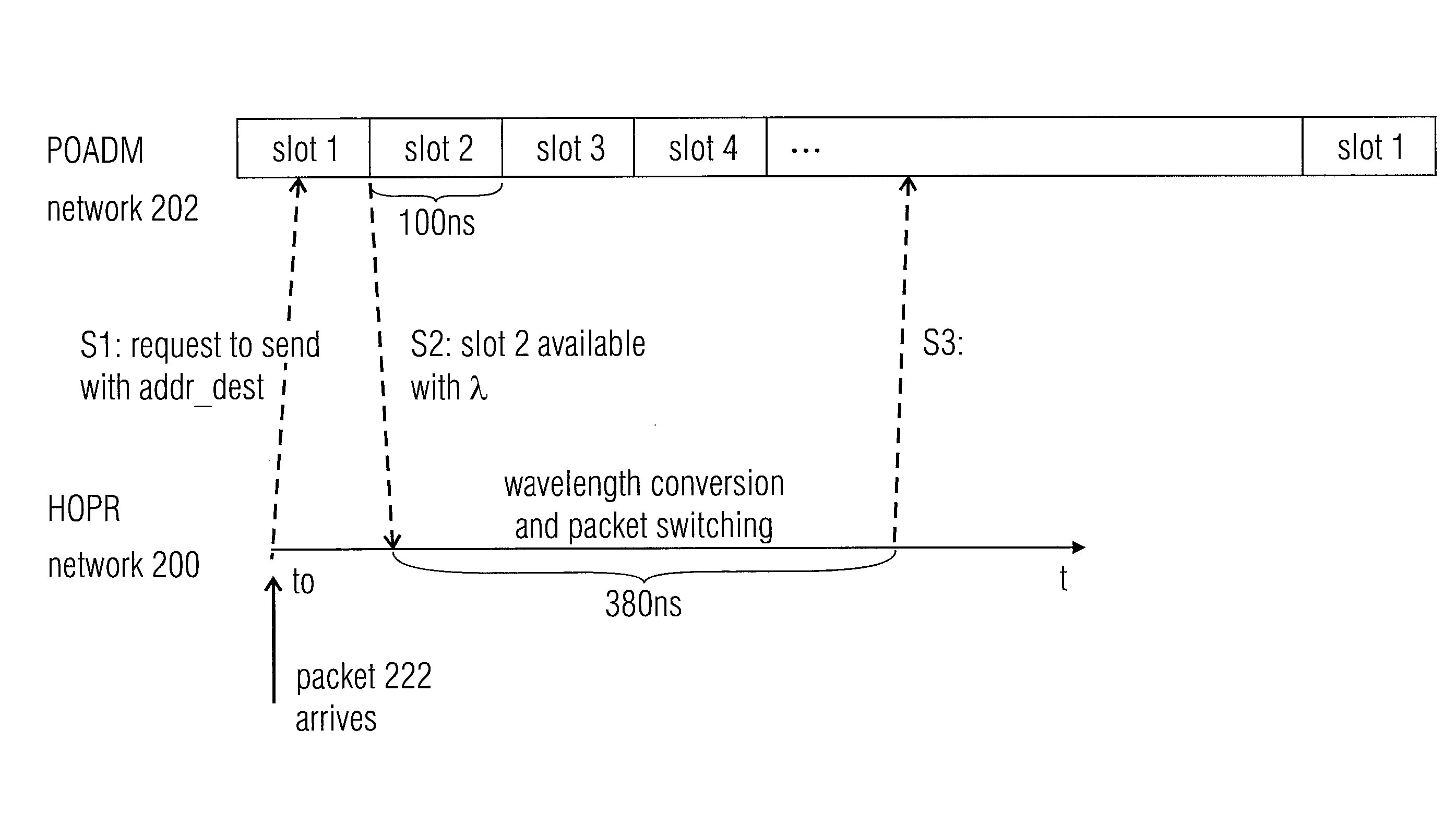
[0033]In the following, embodiments of the present invention for implementing an optical bypass for passing an optical packet optically from an external node, for example a node of a first optical network, to a receiving packet optical network will be described. So far, conventional approaches necessitate the conversion of the optical packet into the electrical domain, processing it and converting it back to the optical domain. To avoid such problems, in accordance with this invention, an optical bypass is provided as mentioned above, however, there are several challenges to realizing such a bypass:

[0034]1. Conversion in the control plane: the two interconnected packet optical networks may have different control mechanisms, for example there may be different addressing schemes, different ways of treating QoS, etc. Further, one of the packet optical networks may have an in-band control channel, while the other one may have a dedicated control channel.

[0035]2. Conversion in the user p...


PUM


Abstract

A method and a system for providing an external optical data packet to a destination node of a packet optical network are described. The packet optical network includes a plurality of nodes and a first optical data channel for optically communicating local optical data packets between the plurality of nodes. The external optical data packet is optically converted for a transmission to the destination node over a second optical data channel of the packet optical network, the first and second optical data channels being independent of each other, the converted external optical data packet is optically transferred to the packet optical network, and the converted external optical data packet is transmitted to the destination node over the second optical data channel.

Description

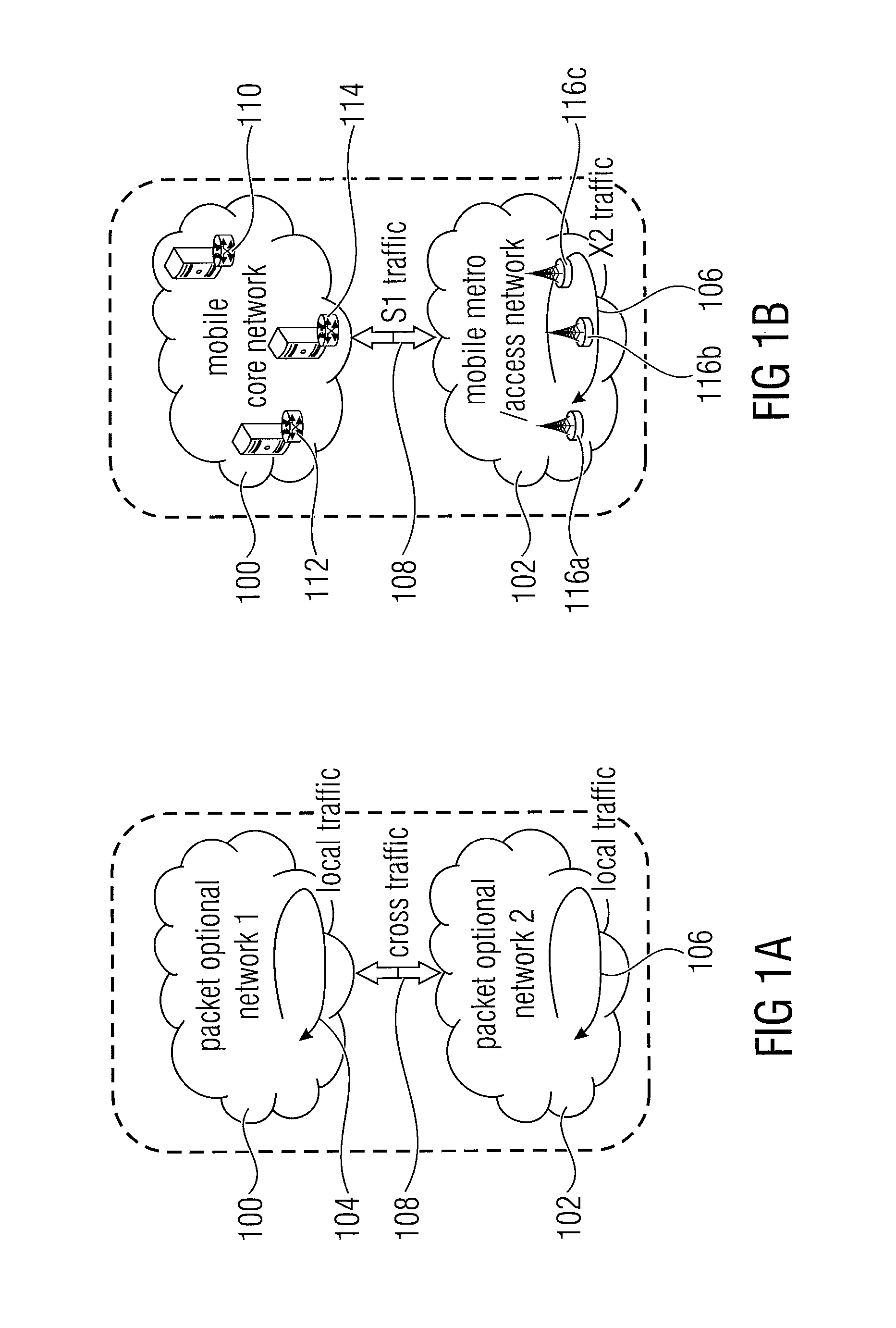
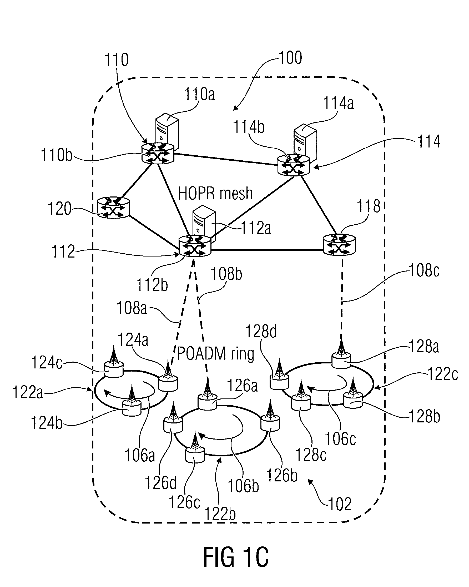
RELATED APPLICATIONS[0001]This application claims priority under 35 U.S.C. §119 to European Patent Application No. 12186801.2 filed on Oct. 1, 2012, the entire content of which is hereby incorporated by reference.BACKGROUND OF THE INVENTION[0002]Embodiments of the invention relate to approaches for allowing an optical packet to be optically provided to a packet optical network, e.g. for allowing an optical communication between two or more packet optical networks enabling an optical bypass between two or more packet optical networks, for example packet optical mobile communication networks.[0003]FIGS. 1A through 1C show examples for optical networks communicating with each other. FIG. 1A is a general representation of two packet optical networks exchanging signals / messages. FIG. 1B is a more detailed representation of the networks being a mobile core network and a mobile metro / access network. FIG. 1C is an even more detailed representation of possible implementations of the mobile n...

Claims


Application Information

Patent Timeline
Patent Type & Authority Applications(United States)
IPC IPC(8): H04J14/02
CPCH04J14/0201H04J14/0257H04J14/0269H04Q11/0066H04J14/0258H04J14/0267H04J14/0283H04J14/0284H04J14/0286H04Q2011/0077
Inventor WEI, QINGKOZU, KAZUYUKI
Owner NTT DOCOMO INC
Learn More