
Solid oxide fuel cell stack with uniform flow distribution structure and metal sealing member

Active Publication Date: 2014-04-03
KOREA INST OF ENERGY RES
View PDF3 Cites 4 Cited by
  • Summary
  • Abstract
  • Description
  • Claims
  • Application Information

AI Technical Summary

Benefits of technology

The present invention aims to solve issues in prior art solid oxide fuel cell stacks by providing heat exchangers to preheat fuel and air before distributing them over the reaction surfaces of unit cells. This ensures uniform supply of reactant gases to each cell and prevents performance degradation. Additionally, a metal sealing member is used to improve sealing effect and increase durability of the fuel cell under high temperature and pressure conditions. Compensating for tolerances in the unit cells can also be achieved by controlling the thickness and number of spacers.

Problems solved by technology

At this time, the voltage of the electricity generated in the unit cell of the fuel cell is not high enough to be useful and thus several cells are typically stacked and connected in series in the form of a stack.
However, in the conventional solid oxide fuel cell having the above-described configuration, the reaction of fuel or air occurs more actively in the unit cells adjacent to an inlet side of the fuel or air channel than in the unit cells adjacent to an outlet side, which thus causes a temperature difference between the inlet side and the outlet side of each unit cell over the entire stack.
On this account, the entire configuration of the system for operating the fuel cell stack is complicated and requires high installation costs.
Moreover, during the operation of the fuel cell stack, the fuel and air preheated by the heat exchangers are not uniformly supplied to the reaction surfaces of the unit cells stacked vertically, which causes a local reaction gas shortage, and thus the reactivity of the stacked unit cells is reduced, thus significantly reducing the efficiency and performance of the fuel cell.
However, when the conventional fuel cell stack using the sealing member made of glass is operated at high temperature and high pressure, a viscous flow of glass occurs, which causes a pressure change in the horizontal direction between the contact surfaces of the unit cell and the stack, thus causing destruction of the unit cells due to the pressure change.

Method used


Image

  • Solid oxide fuel cell stack with uniform flow distribution structure and metal sealing member
  • Solid oxide fuel cell stack with uniform flow distribution structure and metal sealing member
  • Solid oxide fuel cell stack with uniform flow distribution structure and metal sealing member

Examples


Embodiment Construction

[0028]Hereinafter, preferred embodiments of the present invention will be described in detail with reference to the accompanying drawings.

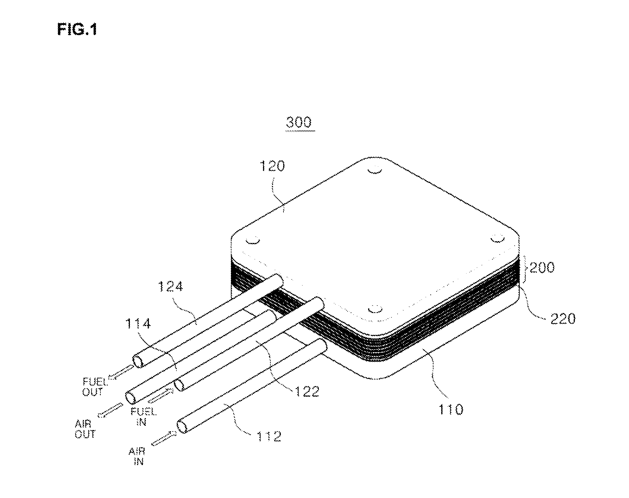
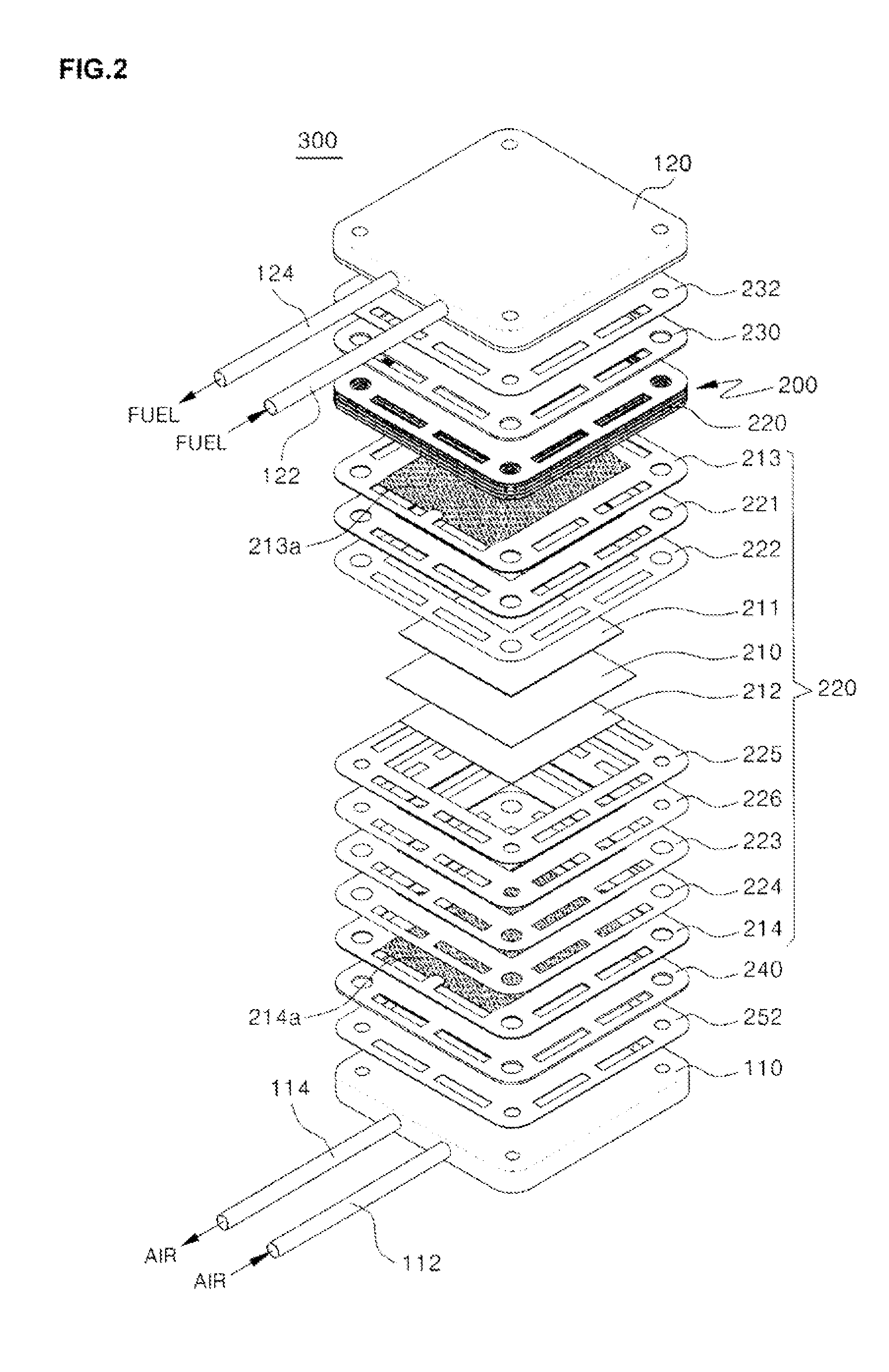
[0029]FIG. 1 is a perspective view showing the structure of a solid oxide fuel cell stack in which five unit cells are stacked according to an embodiment of the present invention, and FIG. 2 is an exploded perspective view of FIG. 1.

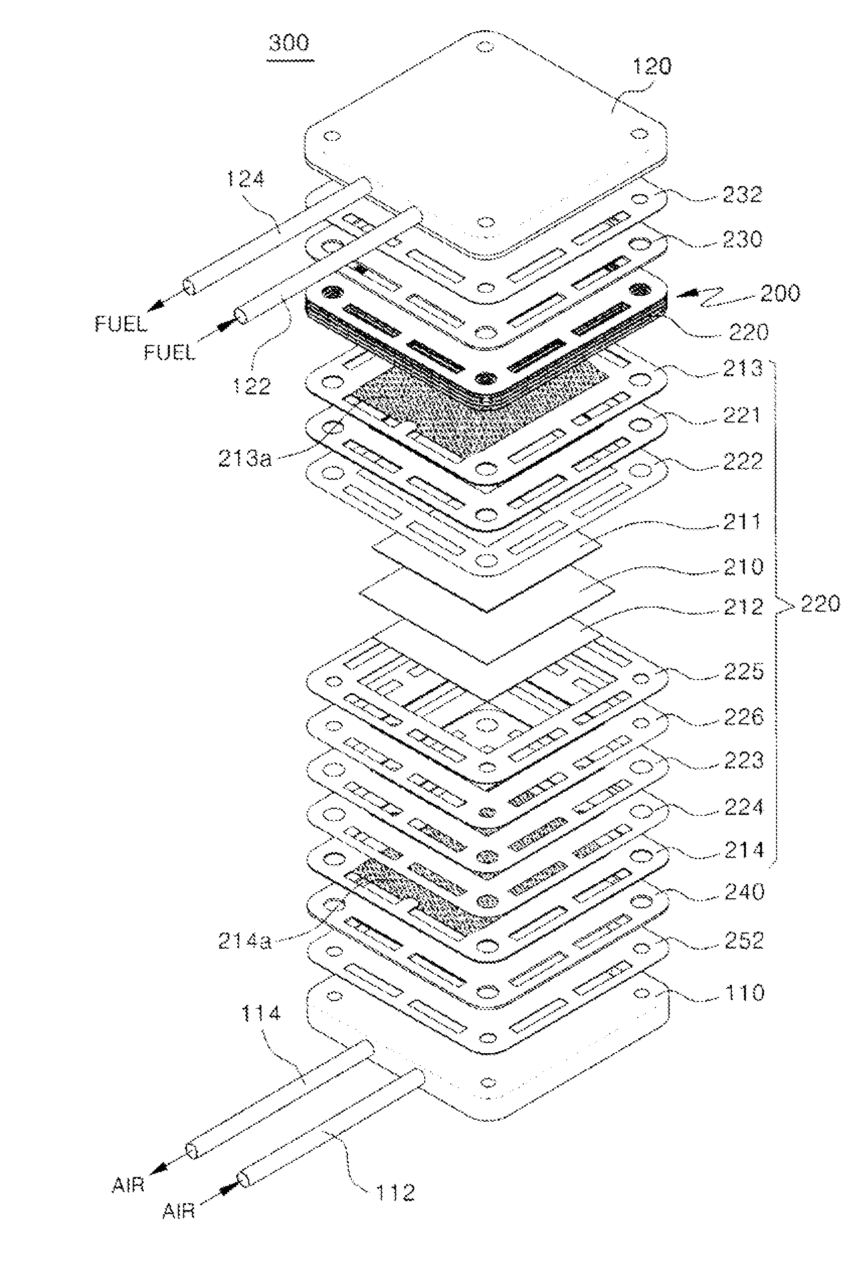
[0030]Referring to FIGS. 1 and 2, a solid oxide fuel cell stack 300 according to the present invention comprises a bottom plate 110 and an upper plate 120, which form the outer surfaces, a cell stack 200 including a plurality of unit cells 220, heat exchangers 230 and 240, and a sealing member made of a metal material.

[0031]An air inlet 112 through which oxygen-containing air is introduced from the outside and an air outlet 114 through which the air reacting with fuel in the cell unit 220 is discharged are provided on one side of the bottom plate 110.

[0032]The upper plate 120 is disposed on an upper side spaced a prede...


PUM


Abstract

A solid oxide fuel cell stack with a uniform flow distribution structure and a metal sealing member is provided, in which fuel and air introduced into the solid oxide fuel cell stack are preheated to a predetermined temperature by heat exchangers provided therein and uniformly distributed over the entire anode and cathode reaction surfaces of unit cells to improve the use efficiency of a fuel cell and in which the sealing of the fuel cell stack is effectively maintained even under high temperature and high pressure conditions to ensure the safety of the fuel cell and increase its durability.a heat exchanger at an anode side configured to preheat fuel introduced through the fuel inlet and uniformly distribute the preheated fuel to the respective unit cells provided in the cell stack; anda sealing member for sealing and electrically insulating between the bottom plate, the lower plate, the unit cells, the heat exchanger at the cathode side, and the heat exchanger at the anode side,wherein the cell stack, the heat exchangers, and the sealing member comprise a plurality of flow passages of fuel and air which are formed to penetrate therethrough, respectively, the flow passages including inlet passages through which the fuel and air are introduced and outlet passages through which the fuel and air are discharged, the inlet passages configured in such a manner that their areas gradually decrease from inlet sides thereof to the insides, the outlet passages configured in such a manner that their areas gradually increases toward outlet sides thereof.9. A fuel cell vehicle comprising the fuel cell system of claim 8.

Description

CROSS-REFERENCE TO RELATED PATENT APPLICATION[0001]This application claims the benefit of Korean Patent Application No. 10-2012-0109076, filed on Sep. 28, 2012, in the Korean Intellectual Property Office, the disclosure of which is incorporated herein in its entirety by reference.BACKGROUND OF THE INVENTION[0002]1. Field of the Invention[0003]The present invention relates to a flat solid oxide fuel cell stack and, more particularly, to a solid oxide fuel cell stack with a uniform flow distribution structure and a metal sealing member, in which fuel and air introduced into the solid oxide fuel cell stack are preheated to a predetermined temperature by heat exchangers provided therein and uniformly distributed over the entire anode and cathode reaction surfaces of unit cells to improve the use efficiency of a fuel cell and in which the sealing of the fuel cell stack is effectively maintained even under high temperature and high pressure conditions to ensure the safety of the fuel cell...

Claims


Application Information

Patent Timeline
IPC IPC(8): H01M8/04H01M8/24
CPCH01M8/04074H01M8/2485H01M8/04201H01M8/0232H01M8/0245H01M8/0282H01M8/2465H01M8/249H01M2008/1293H01M2250/20Y02E60/50Y02T90/40H01M8/04H01M8/12H01M8/24H01M8/2425H01M8/2483
Inventor DONG, SANG KEUNJEONG, WOO NAM
Owner KOREA INST OF ENERGY RES
Learn More