

Bushing for the chamber of a sporting pistol or rifle and manufacturing procedure
- Summary
- Abstract
- Description
- Claims
- Application Information
AI Technical Summary
Benefits of technology
Problems solved by technology
Method used
Image

Examples
Embodiment Construction
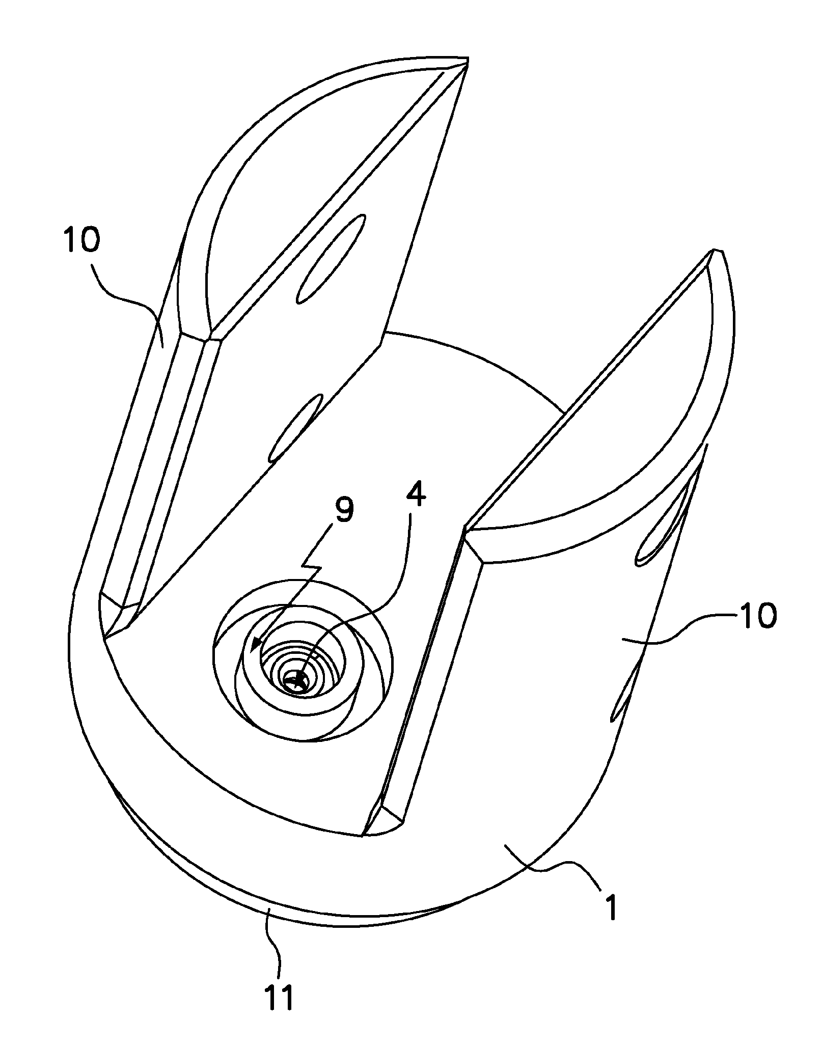
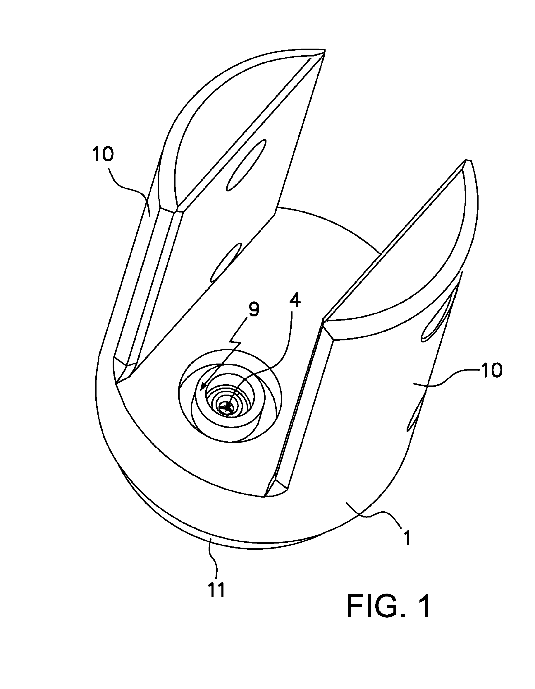
[0021]In this way, FIG. 1 represents bushing 1 in the form of a fork with its extensions 10, an exit orifice 4 and cavity 9.
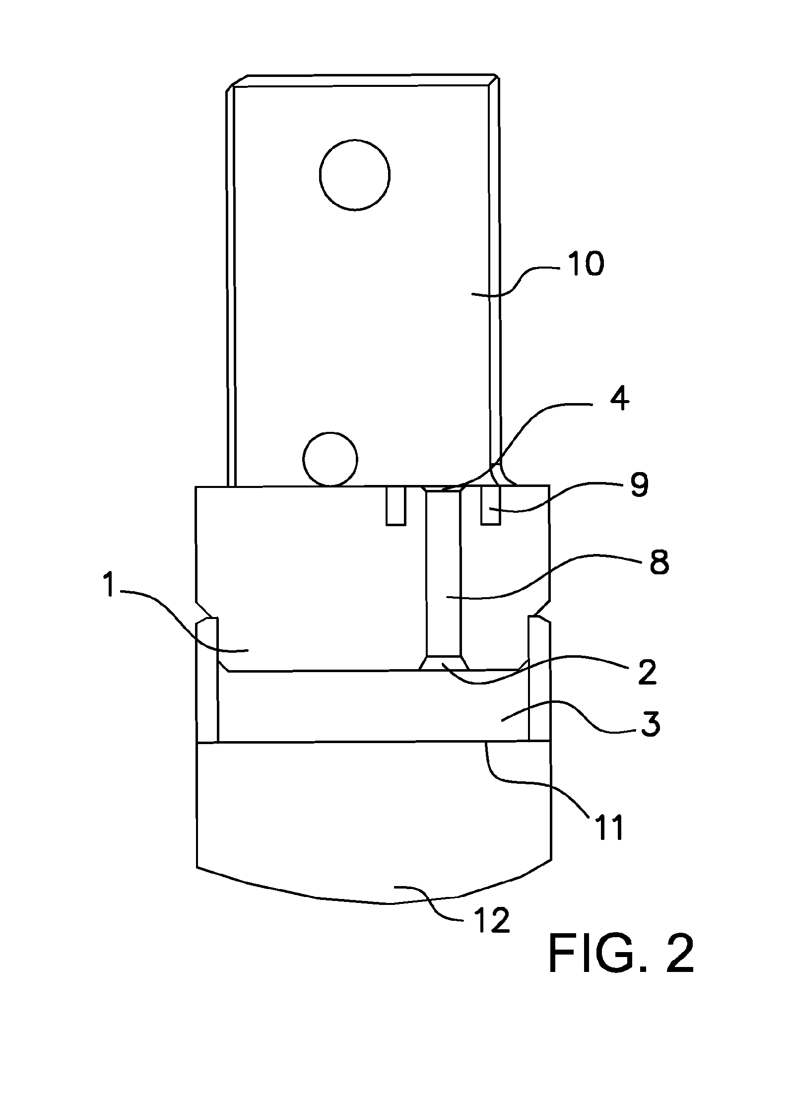
[0022]FIG. 2 illustrates bushing 1 with its extensions 10, rifle chamber 12, entrance orifice 2, a connection passage 8, exit orifice 4, cavity 9 and compression chamber 3.
[0023]FIG. 3 shows bushing 1 with its extensions 10, rifle chamber 12, entrance orifice 2, connection passage 8, exit orifice 4, cavity 9, compression chamber 3, a tool 5, a striker 6 and centring element 7.
[0024]FIG. 4 represents bushing 1 with its extensions 10, rifle chamber 12, entrance orifice 2, connection passage 8, exit orifice 4, cavity 9, compression chamber 3, tool 5, plunger 6 and centring element 7.
[0025]Lastly, FIG. 5 illustrates bushing 1 with its extensions 10, rifle chamber 12, entrance orifice 2, connection passage 8, exit orifice 4, cavity 9 and compression chamber 3.
[0026]It is necessary to point out that bushing 1 is an embodiment like the one described in the following p...
PUM
| Property | Measurement | Unit |
|---|---|---|
| Power | aaaaa | aaaaa |
| Diameter | aaaaa | aaaaa |
| Shape | aaaaa | aaaaa |
Abstract
Description
Claims
Application Information