Magnetic powder, forming method thereof and magnetic sheet
- Summary
- Abstract
- Description
- Claims
- Application Information
AI Technical Summary
Benefits of technology
Problems solved by technology
Method used
Image
Examples
first embodiment
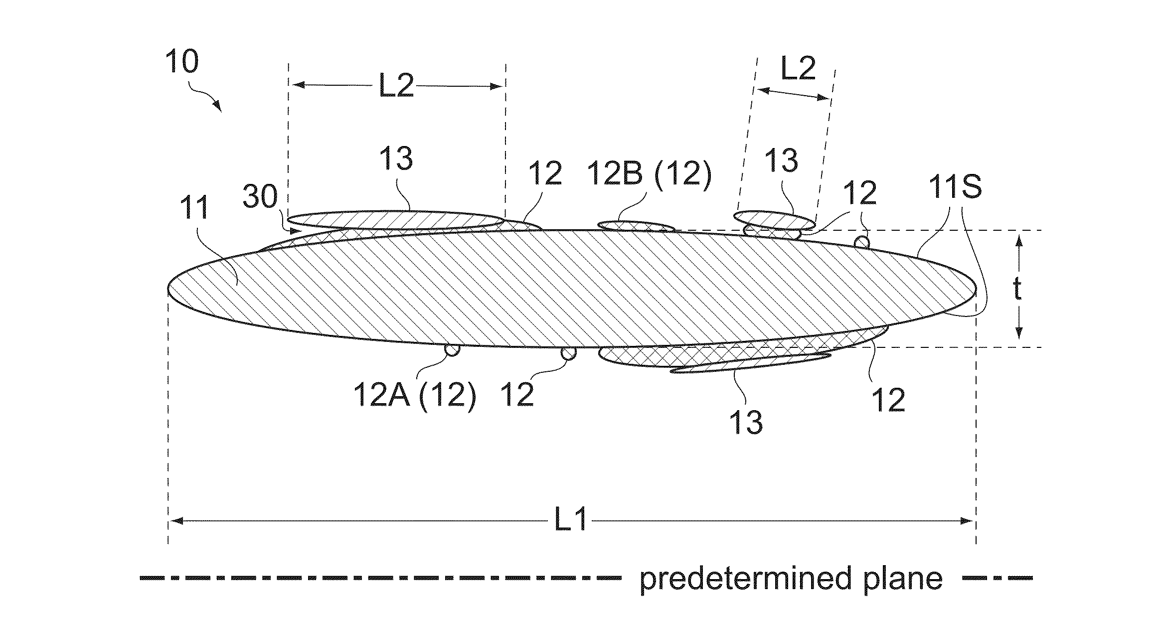
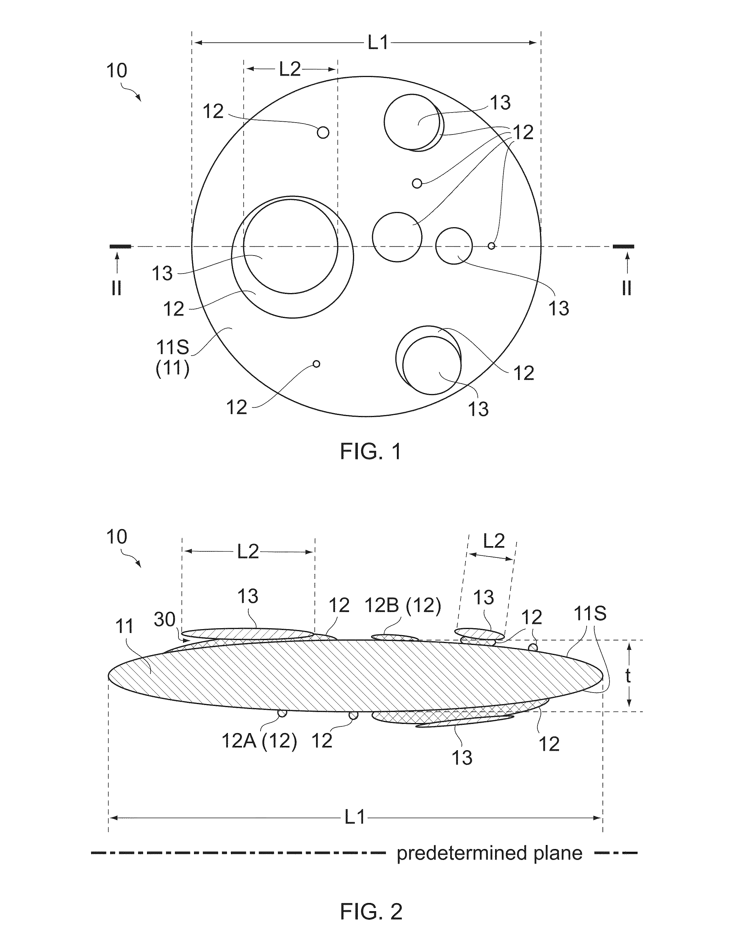
[0020]As shown in FIGS. 1 and 2, a magnetic powder (magnetic powder particle) 10 according to a first embodiment of the present invention comprises a first magnetic particle (magnetic particle) 11 made of a soft magnetic metal, one or more inorganic insulating particles 12 and one or more second magnetic particles (magnetic particles) 13 each made of a soft magnetic metal.
[0021]The first magnetic particle 11 has a flat shape with surfaces 11S. Each of the surfaces 11S illustrated in FIG. 2 is a curved surface. However, surface 11S may be a flat surface which is in parallel to a predetermined plane (see FIG. 2). In other words, the first magnetic particle 11 may extend in parallel to the predetermined plane. The inorganic insulating particles 12 are attached to the first magnetic particle 11. In detail, the inorganic insulating particles 12 include one or more inorganic insulating particles 12A and one or more inorganic insulating particles 12B. The inorganic insulating particle 12A ...
second embodiment
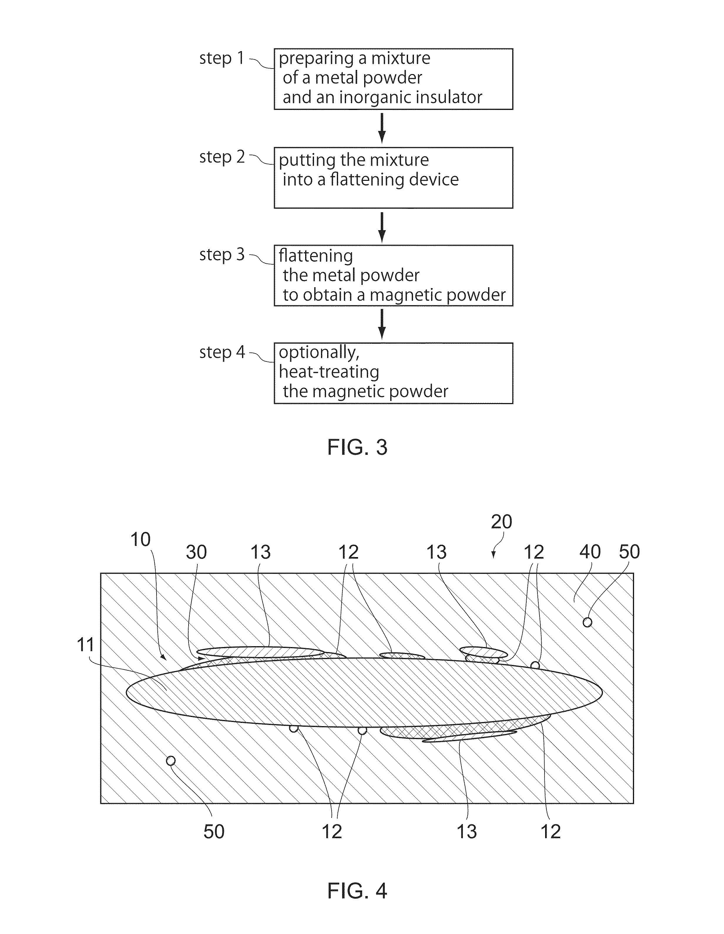
[0042]As shown in FIG. 4, a magnetic sheet 20 according to a second embodiment of the present invention comprises a plurality of the magnetic powder particles 10 and a binder 40 made of a polymer. The magnetic sheet 20 has flexibility. The binder 40 binds the magnetic powder particles 10 so as to generate the flexibility of the magnetic sheet 20.
[0043]The magnetic sheet 20 shown in FIG. 4 can be formed via the following steps.
[0044]At first, the magnetic powder 10 according to the first embodiment is mixed with a liquid binder. Then, the binder, which includes the magnetic powder 10, is deposited to form a sheet. Then, the sheet of the binder is solidified to become the binder 40 so that the magnetic sheet 20 is formed. The binder 40 is made of a polymer so that the flexibility of the magnetic sheet 20 can be obtained.
[0045]The liquid binder can be solidified by using various methods. For example, the liquid binder including the magnetic powder 10 may be mixed with an organic solven...
examples
Preparing a Mixture of Example 1
[0054]A mixture of metal powder particles and an inorganic insulator was prepared. The metal powder particle was made of an amorphous Fe—P-B—Nb—CR alloy. Each of the metal powders had a sphere-like shape and soft magnetism. The inorganic insulator was a glass frit made of a phosphate. The phosphate was an oxide including Si, Al, P, Na, K, Ca, Zn and Sb. The metal powder particles and the inorganic insulator were mixed with a solvent so that the mixture (i.e. mix powder) of the metal powder particles and the inorganic insulator was obtained.
[0055]The metal powder particle had a crystallization temperature of 490° C. The inorganic insulator had a softening point of 365° C.
[0056](Putting the Mixture of Example 1 in a Flattening Device)
[0057]The mix powder including the solvent was put into a ball mill.
[0058](Flattening the Metal Powder Particles of Example 1)
[0059]The metal powder particles of the mix powder were flattened by using the ball mill so that ...
PUM
| Property | Measurement | Unit |
|---|---|---|
| Length | aaaaa | aaaaa |
| Length | aaaaa | aaaaa |
| Length | aaaaa | aaaaa |
Abstract
Description
Claims
Application Information
 - Generate Ideas
- Intellectual Property
- Life Sciences
- Materials
- Tech Scout
- Unparalleled Data Quality
- Higher Quality Content
- 60% Fewer Hallucinations
Browse by: Latest US Patents, China's latest patents, Technical Efficacy Thesaurus, Application Domain, Technology Topic, Popular Technical Reports.
© 2025 PatSnap. All rights reserved.Legal|Privacy policy|Modern Slavery Act Transparency Statement|Sitemap|About US| Contact US: help@patsnap.com


