Apparatus and Method for Measuring the Thickness of a Measurement Object

a technology for measuring objects and apparatus, applied in the direction of mechanical measuring arrangements, instruments, caliper-like sensors, etc., can solve the problems of critical predefined distance between the two measurement sensors, inability to mechanically stabilize the c-brackets and/or o-frames over the width of the sheet material, and inconvenient use of the measurement object, so as to prevent the wear of the measurement sensor

Active Publication Date: 2014-04-17
MICRO EPSILON MESSTECHNIK GMBH & CO KG
View PDF14 Cites 16 Cited by
  • Summary
  • Abstract
  • Description
  • Claims
  • Application Information

AI Technical Summary

Benefits of technology

[0013]Therefore, the present invention addresses the problem of designing and realizing a device and a method for measuring the thickness of a measurement object, in the class named above, in such a manner that in industrial applications a robust measurement mechanism is ensured, which is suitable for industry and which provides high measurement precision, with constructively simple and cost-effective means.

Problems solved by technology

However, in the case of thickness measurement for wide, sheet-shaped materials, particularly coils, inner liners, etc., the predefined distance between the two measurement sensors is critical.
Particularly for the measurement of metallic strips in widths up to 1-2 m, or paper webs up to 6 m in width or more, it is particularly problematic that C-brackets and / or O-frames cannot be held in a mechanically stable manner over the width of the sheet material serving as the measurement object.
As a result, the distance between the distance measurement sensors is not constant.
As such, the distance between the distance measurement sensors is altered due to vibration or longitudinal expansion of the machine frame caused by thermal input.
As a result, for thickness measurements which commonly require precision within micrometers, it is not possible to make a precise measurement, due to the action of vibration and / or temperature.
However, the use of vibration-resistant or temperature-stable O-frames and / or C-frames, to prevent imprecision in measurement, demands a great deal of mechanical complexity and special materials, such as Invar (registered trademark), for example, which results in considerable costs.
In addition, it is only possible to measure the calibration part in short intervals outside of the material sheet.
As a result, it is not possible to detect and compensate a change in the measurement gap over the material.
However, this embodiment has the significant disadvantage that, in the case of a C-frame with long sides, the installation of the measurement sensors requires a great deal of time and effort.
In addition, in the design using glass, it is very problematic that glass can brake very easily and is therefore not suited for use in rough industrial production applications.
However, the known device has the problem that the optical sensors are not suited for industrial use in what is typically a rough production environment, because the optical sensors are subjected to vibrations, shock, contamination, etc. in this environment.
In addition, it is difficult to precisely orient the lasers.
A further disadvantage of the known device is that, as a result of the lasers being mounted on one side, even the smallest movements result in a misalignment of the beams, and this misalignment becomes larger as the sensors become farther from the beam source.

Method used


Image

  • Apparatus and Method for Measuring the Thickness of a Measurement Object
  • Apparatus and Method for Measuring the Thickness of a Measurement Object
  • Apparatus and Method for Measuring the Thickness of a Measurement Object

Examples


Embodiment Construction

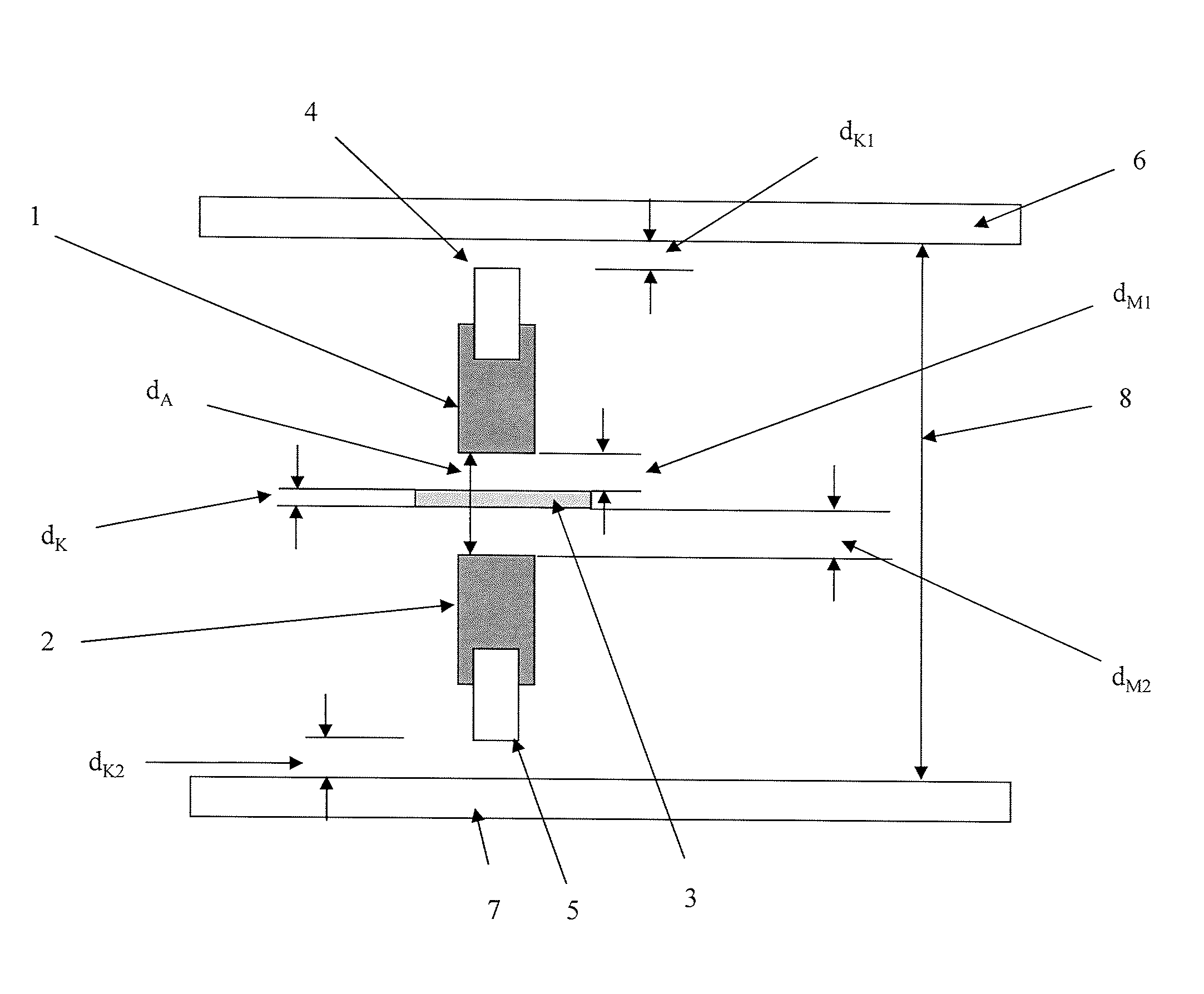
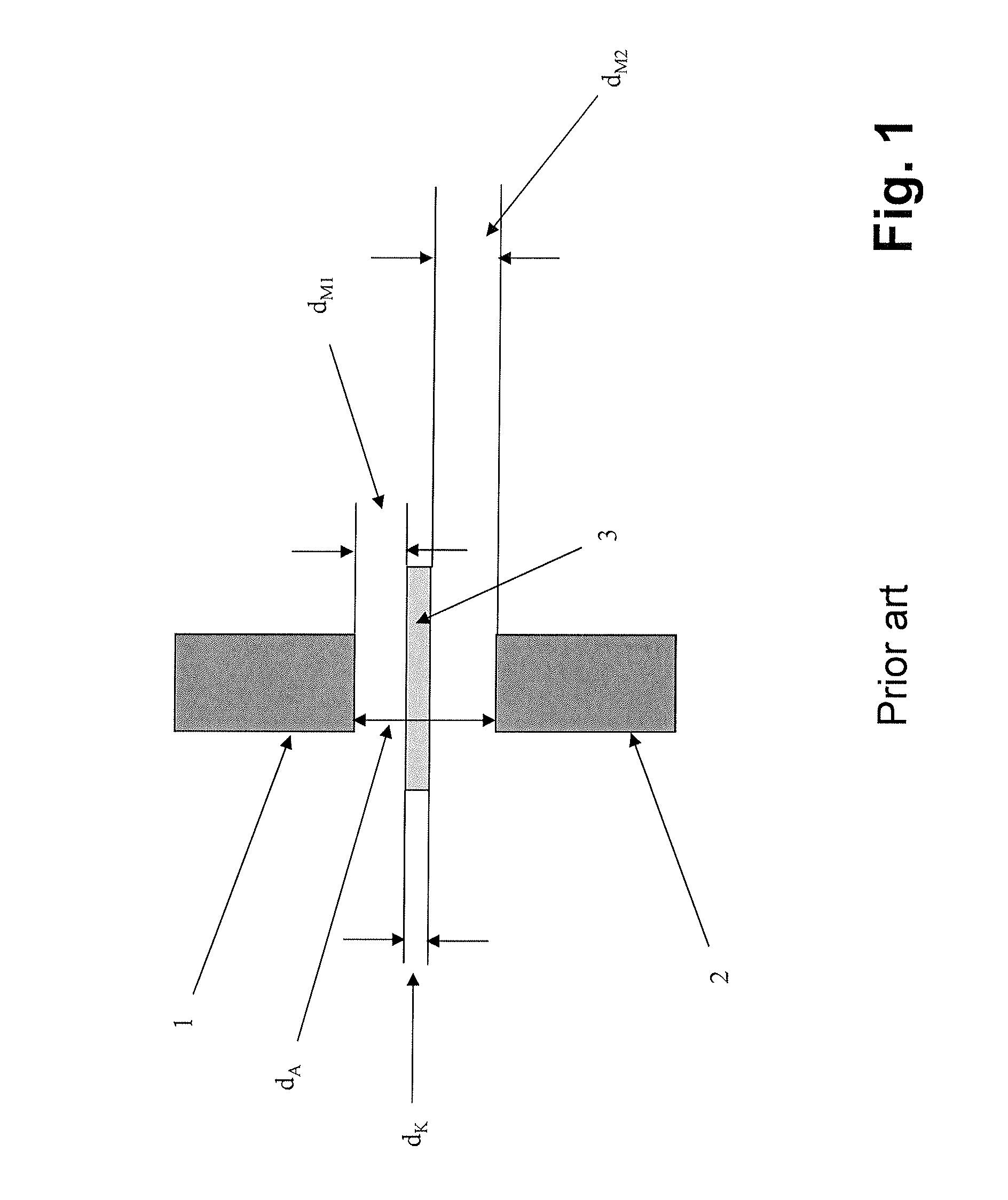
[0045]FIG. 1 shows a schematic illustration of the basic principle of differential thickness measurement and / or calibration known from the prior art, by means of two distance measurement sensors and a sensor- and calibration arrangement. Each of the distance measurement sensors 1 and 2 takes a measurement relative to the upper or lower surface of the measurement object. The thickness is found by subtracting from the measurement gap dA each measurement reading dM1 and dM2. The basic precondition for a correct thickness measurement reading is that the measurement gap dA, meaning the distance between the two distance measurement sensors 1 and 2, remains constant. This could be achieved by a suitable suspension and guidance of the distance measurement sensors 1 and 2, which nevertheless means great time and effort in the selection of the materials (high-strength, temperature stable materials) and the construction.

[0046]It is substantially simpler, more cost-effective, and more precise i...


PUM


Abstract

An apparatus for measuring the thickness of a measurement object, preferably a measurement object in the form of a web or piece goods, in a measuring gap, with a measuring mechanism which is fitted to a machine frame, wherein the measuring mechanism for measuring the thickness comprises one or more travel measurement sensor(s) aimed at the measurement object, is characterized in that a compensation sensor which is coupled to a travel measurement sensor measures the distance to a reference rule in order to detect and compensate for a change in the measuring gap, in that the reference rule is in the form of a side of a frame-shaped reference device integrated in the measuring mechanism, and in that the reference device is configured in such a manner that the distance between the reference rule and that side of the reference device which is opposite the reference rule is known during the thickness measurement. A corresponding method for measuring the thickness is also stated.

Description

CROSS REFERENCE TO RELATED APPLICATIONS[0001]This application is a national stage application, filed under 35 U.S.C. §371, of International Application No. PCT / DE2012 / 200018, filed Mar. 27, 2012, which claims priority to and the benefit of German Application No. 10 2011 017 297.1, filed Apr. 15, 2011, and German Application No. 10 2011 107 771.9, filed Jul. 15, 2011, the contents of all of which are hereby incorporated by reference in their entirety.BACKGROUND[0002]1. Technical Field[0003]The invention relates to a device for measuring the thickness of a measurement object, the same for example having the shape of a sheet or cargo goods, in a measuring gap, by means of or via a measuring mechanism attached on a machine frame, wherein the measuring mechanism has one or more distance measurement sensors oriented toward the measurement object, for the purpose of measuring the thickness thereof.[0004]In addition, the invention relates to a method for measuring the thickness of a measure...

Claims


Application Information

Patent Timeline
Patent Type & Authority Applications(United States)
IPC IPC(8): G01B5/06
CPCG01B5/06G01B7/06G01B7/087G01B7/107G01B11/06G01B11/0691G01B21/08G01B2210/44
Inventor SONNTAG, ACHIMKIRSCHNER, GERHARTFUELLMEIER, HERBERTHOCHWIMMER, FRANZ
Owner MICRO EPSILON MESSTECHNIK GMBH & CO KG
Why Eureka
Try Eureka