Pressure measurement device and liquid treatment device

a technology of pressure measurement device and liquid treatment device, which is applied in the direction of fluid pressure measurement by mechanical elements, fluid pressure measurement using elastically deformable gauges, instruments, etc., can solve the problems of high accuracy required in the manufacturing process, limited use environment, and inconvenient operation

Inactive Publication Date: 2014-04-17
SEIKO EPSON CORP
View PDF4 Cites 7 Cited by
  • Summary
  • Abstract
  • Description
  • Claims
  • Application Information

AI Technical Summary

Benefits of technology

[0007]An advantage of some aspects of the invention is to solve at least a part of ...

Problems solved by technology

Therefore, there has been pointed a problem that an extremely high accuracy is required in the manufacturing process in order to accurately measure the pressure.
Further, there has been also pointed a problem that it is also required to frequently perform the calibration when using the tuning-fork vibrator.
Since the behav...

Method used


Image

  • Pressure measurement device and liquid treatment device
  • Pressure measurement device and liquid treatment device
  • Pressure measurement device and liquid treatment device

Examples


first embodiment

A. First Embodiment

A1. System Configuration

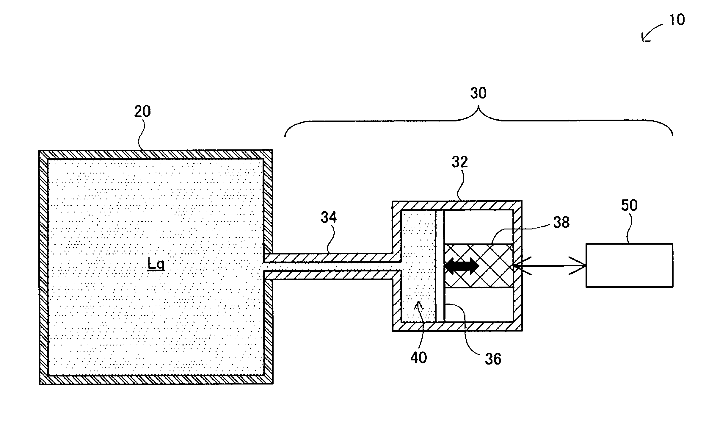
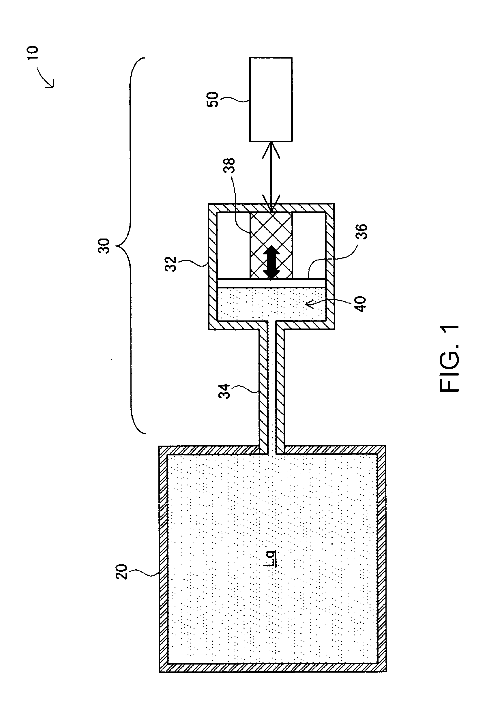
[0031]FIG. 1 is an explanatory diagram for explaining a measurement system 10 using a pressure measurement device 30 according to a first embodiment of the invention. The pressure measurement device 30 is a device for measuring the pressure of a liquid. The measurement system 10 is provided with a container 20 containing a liquid Lq as a measurement target, and the pressure measurement device 30. In the present embodiment, the liquid Lq contained in the container 20 is water. The inside of the container 20 is kept at a predetermined pressure.

[0032]The pressure measurement device 30 is provided with a housing 32, a flow channel 34, a diaphragm 36, a piezoelectric element 38, and a drive circuit 50. The housing 32 has a pump chamber 40 inside. The pump chamber 40 is constituted by an inner wall of the housing 32 and a diaphragm 36. The flow channel 34 is connected to the container 20 to make the pump chamber 40 and the container 20 communicat...

second embodiment

B. Second Embodiment

B1. System Configuration

[0055]Since the configuration of the measurement system 10 using the pressure measurement device 30 according to the second embodiment of the invention is substantially the same as that in the first embodiment (FIG. 1), the graphical description and the illustration thereof will be omitted. It should be noted that the second embodiment is different in the configuration of the drive circuit 50 from the first embodiment.

[0056]FIG. 5 is a block diagram for explaining the configuration of the drive circuit 50 in the second embodiment. Further, FIGS. 6A through 6D are diagrams showing signal waveforms of the drive circuit 50. The drive circuit 50 is provided with the control section 52 for outputting the drive waveform signal Vin, the amplifier circuit 54 for amplifying the drive waveform signal Vin at the gain G to output the drive signal Vout, a pressure variation rate detection section 80 for detecting a variation rate of the internal pressu...

modified example 1

C1. Modified Example 1

[0071]Although in each of the embodiments described above, it is assumed that the pressure of the water contained in the container 20 is measured, the invention is not limited to the case in which the liquid Lq as the measurement target is contained in a sealed container, but it is also possible to arrange that the liquid Lq is contained in a pipe or an open container. Even in such a case, the pressure measurement device 30 can measure the pressure of the liquid Lq.


PUM


Abstract

A pressure measurement device adapted to measure a pressure of a liquid includes a flow channel having a flow channel resistance, a liquid containing chamber having a predetermined capacity and communicating with the flow channel, a pressure changing section adapted to change a pressure of the liquid containing chamber, a measurement section adapted to measure a period from when a pressure wave of the liquid in the liquid containing chamber becomes a predetermined value to next time the pressure wave becomes the predetermined value, the pressure wave occurring when the pressure changing section is in operation in a state in which the liquid is contained in the flow channel and the liquid containing chamber, and an acquisition section adapted to obtain the pressure based on the period measured by the measurement section.

Description

CROSS-REFERENCE TO RELATED APPLICATIONS[0001]This application claims priority to Japanese Patent Application No. 2012-229057 filed on Oct. 16, 2012 and to Japanese Patent Application No. 2013-050265 filed on Mar. 13, 2013. The entire disclosures of Japanese Patent Application No. 2012-229057 and Japanese Patent Application No. 2013-050265 are hereby incorporated herein by reference.BACKGROUND[0002]1. Technical Field[0003]The present invention relates to a technology for measuring the pressure of a liquid.[0004]2. Related Art[0005]In the past, as a technology for measuring the pressure of a liquid, there has been known a technology of, for example, JP-A-2010-85377 (Document 1). In Document 1, there is described a technology of measuring the pressure using a CI value (an equivalent series resistance) of a tuning-fork piezoelectric vibrator.[0006]However, in the technology of the pressure measurement in Document 1, the CI value significantly depends on the physical property characteris...

Claims


Application Information

Patent Timeline
IPC IPC(8): G01L7/08
CPCG01L7/08G01L9/008
Inventor OSHIMA, ATSUSHI
Owner SEIKO EPSON CORP
Why Eureka
Try Eureka