Popcorn Making Machine with Various Configurations of Roaster

a popcorn making machine and roaster technology, applied in the field of popcorn preparation machines, can solve the problems of over-drying popcorn, over-paying for electric power, over-drying popcorn, etc., and achieve the effect of reducing the cost of manufacturing of popcorn and simplifying the design of hot-air popcorn making machines

Inactive Publication Date: 2014-04-17
KORIN MIKHAIL
View PDF12 Cites 1 Cited by
  • Summary
  • Abstract
  • Description
  • Claims
  • Application Information

AI Technical Summary

Benefits of technology

[0012]Therefore, one aim of the claimed invention is to simplify the design of hot-air popcorn making machine and reduce the costs for manufacturing thereof.

Problems solved by technology

This leads to over-drying popcorn and overpaying for electric power.
Designers of popcorn making machines often encounter a common problem particularly described in Nakamura: “In a typical popcorn processing machine known heretofore, a receiving dish or pan into which corn kernels are charged is provided above a heat source.
The oil and corn particles thus adhere to the glass cover, thereby dirtying the glass and causing it to become opaque.
Furthermore, if these contaminants are left in adhering state, they will attract undesirable insects such as cockroaches and are therefore very unhygienic.
Since an opaque condition of the glass cover prevents or obstructs observation of the corn popping progress, the contaminants must be frequently wiped off by hand, which is an inconvenient task.
However, if oil is not used in order to prevent this contamination, the time for popping the raw corn becomes disadvantageously long.
Furthermore, the construction of the machine itself in this case has been complicated because of the necessity of providing rotational support means and driving means for the agitator vanes.”
Thereafter, “the popped popcorn product can be quickly dumped and the chamber bottom rapidly reclosed, the operational cycle time thereby being extremely short.” However, the “whirling rising vortex” conditions an increased density of kernels in the lower central region of the chamber, wherein the speed of kernels and temperature of hot air are essentially minimal, which leads to uneven heating the kernels located in this region that slows down the overall heating of corn kernels in the chamber thereby decelerating the whole process of popcorn preparation.
Besides, the movable bottom of the heating chamber reduces the overall reliability and maintainability of the Nakamura's machine.
Nonetheless, exploitation and maintenance of the popcorn machine according to U.S. Pat. No. 8,276,504 have revealed certain inconveniences.

Method used


Image

  • Popcorn Making Machine with Various Configurations of Roaster
  • Popcorn Making Machine with Various Configurations of Roaster
  • Popcorn Making Machine with Various Configurations of Roaster

Examples


first preferred embodiment

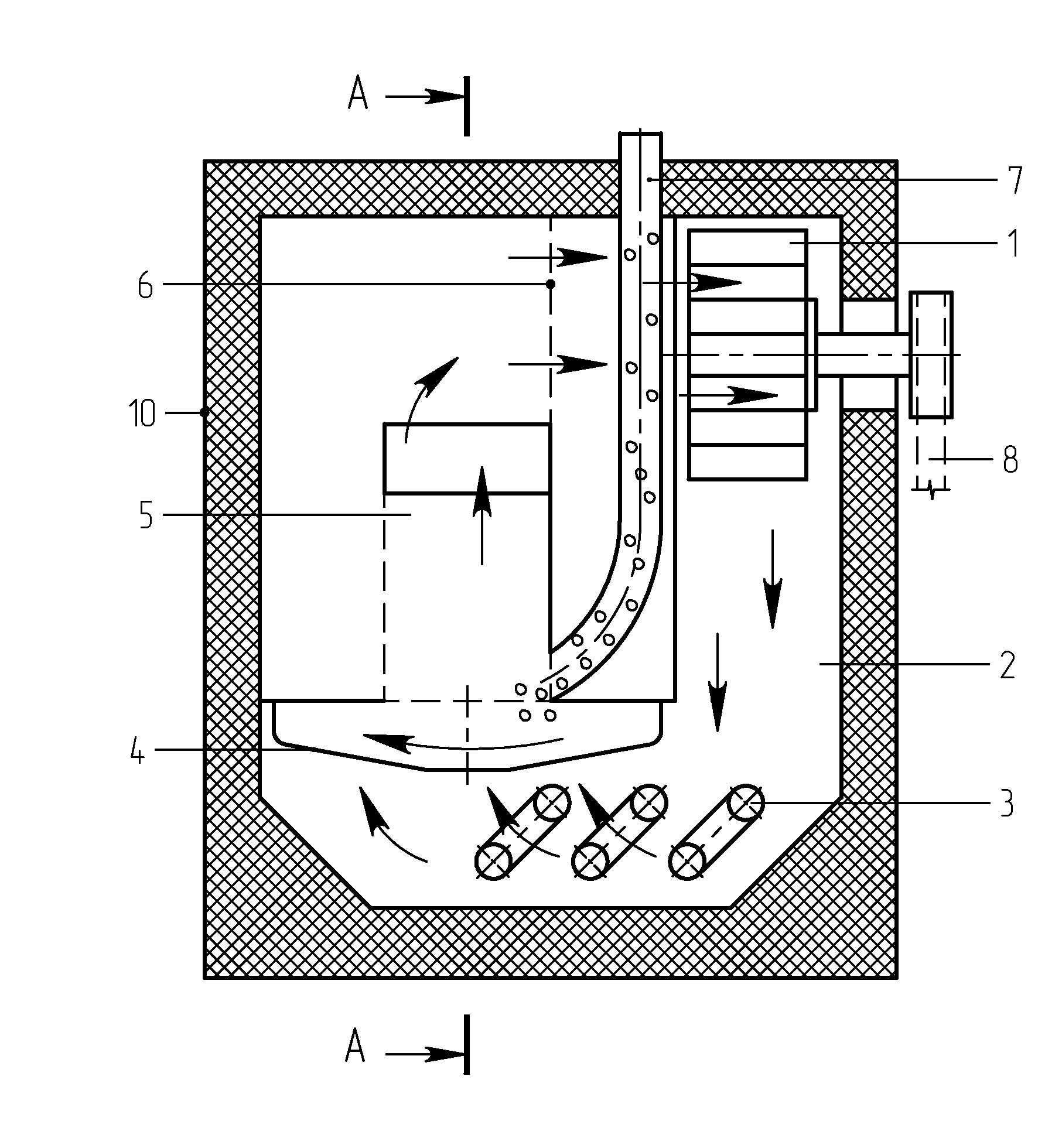
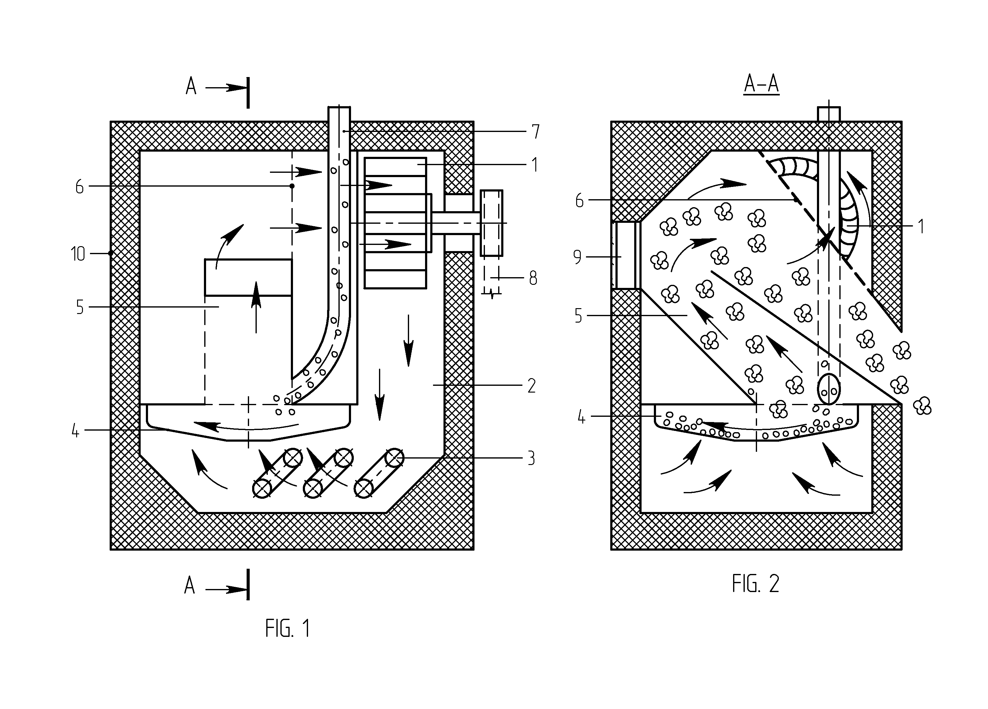
[0028]In a first preferred embodiment, illustrated on FIGS. 1, 2 and 5, the inventive popcorn making machine includes a main unit 100 comprising: a case 2 with a top lid and a bottom; a fan 1 driven by a drive 8 (that may preferably include an electric motor—not shown, and a transmission, for example, a belt transmission); the fan 1 is capable of pumping air via a net screen 6 inside the case 2 that encloses a roaster 4 (can also be called a ‘kettle’ or a ‘cooker’), and a heater 3 that can be represented by any suitable type of conventional heater, preferably an electric coil outwardly surrounding the roaster's sidewalls (as shown on FIG. 1), and powered preferably from a suitable electrical source, not shown herein, preferably supplying controllable voltage. The heater 3 is preferably mounted at the heating chamber's bottom, beneath the roaster 4. The net screen 6 prevents getting popped up corn kernels to the fan 1.

[0029]The roaster 4 has an upper opening, a bottom, and sidewalls ...

second preferred embodiment

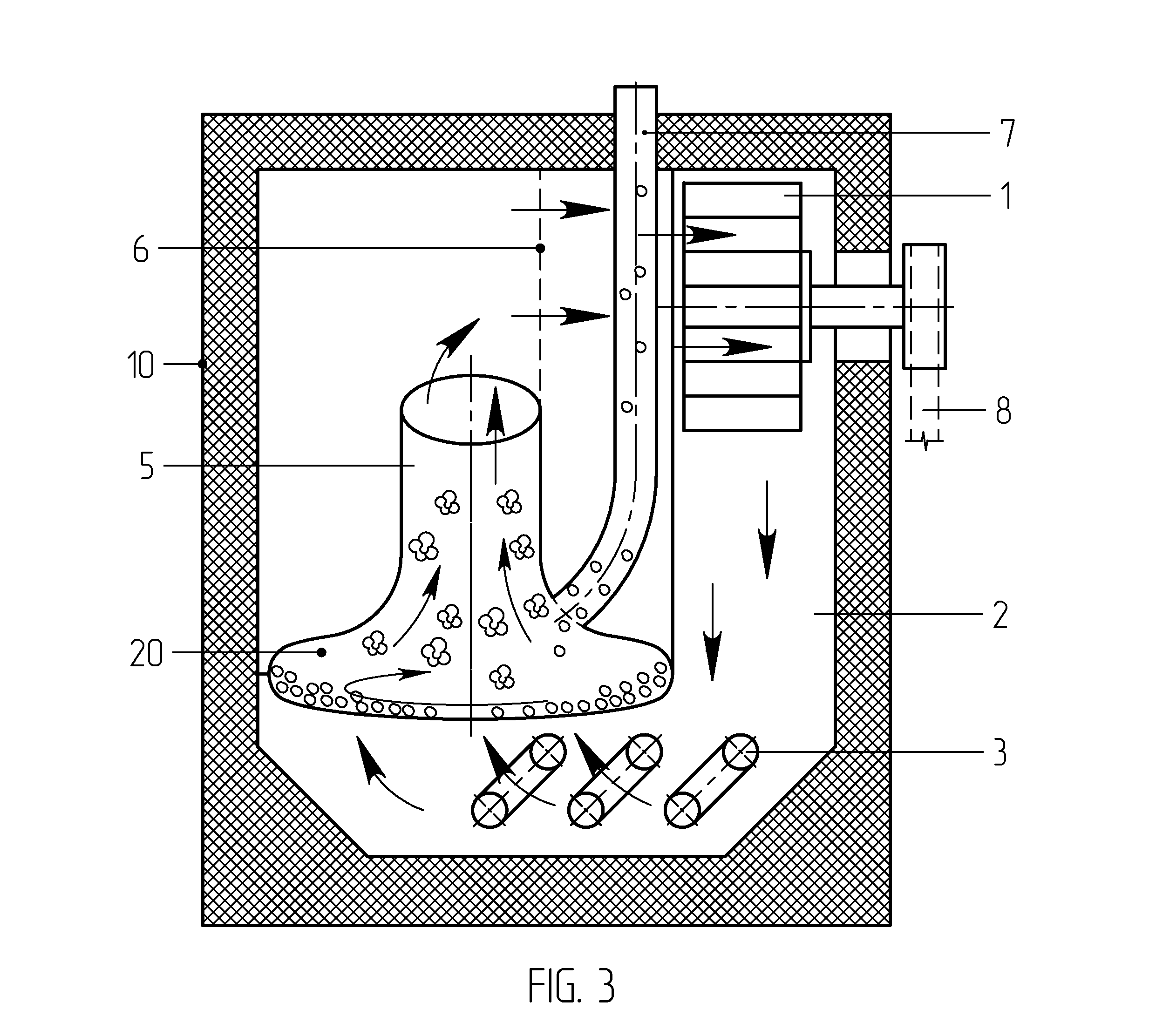
[0031]The second preferred embodiment of the inventive popcorn making machine has a design (illustrated on FIGS. 3 and 6) similar to the first one described above, except for the shapes of roaster and pipebranch. In the second preferred embodiment, the inventive popcorn making machine includes a main unit 100 comprising: a case 2 with a top lid and a bottom; a fan 1 driven by a drive 8 (that may preferably include an electric motor—not shown, and a transmission, for example, a belt transmission); the fan 1 is capable of pumping air via a net screen 6 inside the case 2 that encloses a roaster 20 (can also be called a ‘kettle’ or a ‘cooker’), and a heater 3 that can be represented by any suitable type of conventional heater, preferably an electric coil outwardly surrounding the roaster's sidewalls (as shown on FIG. 3), and powered preferably from a suitable electrical source, not shown herein, preferably supplying controllable voltage. The heater 3 is preferably mounted at the case's ...

third preferred embodiment

[0034]The third preferred embodiment of the inventive popcorn making machine has a design (illustrated on FIGS. 4 and 7) similar to the first one described above, except for the shapes of roaster and pipebranch. In the third preferred embodiment, the inventive popcorn making machine includes a main unit 100 comprising: a case 2 with a top lid and a bottom; a fan 1 driven by a drive 8 (that may preferably include an electric motor—not shown, and a transmission, for example, a belt transmission); the fan 1 is capable of pumping air via a net screen 6 inside the case 2 that encloses a roaster 30 (can also be called a ‘kettle’ or a ‘cooker’), and a heater 3 that can be represented by any suitable type of conventional heater, preferably an electric coil outwardly surrounding the roaster's sidewalls (as shown on FIG. 4), and powered preferably from a suitable electrical source, not shown herein, preferably supplying controllable voltage. The heater 3 is preferably mounted at the case's bo...


PUM


Abstract

A popcorn making machine is proposed in three embodiments including a roaster, provided with a circulated hot airflow, and a pipebranch coupled thereto, receiving popcorn from the roaster and discharging thereof. In the first embodiment, the roaster has truncated conical sidewalls, the pipebranch has a rectangular cross-section. In the second embodiment the roaster is configured as at least a portion of a deformed sphere having a lesser pole radius and a greater equator radius, the pipebranch is conjugated with the roaster without any acute angle, and continuously tapers transforming into a cylindrical shape. In the third preferred embodiment, the roaster and pipebranch are similar to the ones of the second embodiment, but the roaster additionally contains a central cavity configured in a cone-like shape, having a base, a cupola-like top, and a curved conjugation angle at the base. The aforementioned shapes reduce manufacturing costs and improve the popcorn machine's productivity.

Description

FIELD OF THE INVENTION[0001]This invention relates to corn popping machines, particularly to popcorn preparation machines utilizing the continuous popping of corn kernels by means of a hot airflow.BACKGROUND OF THE INVENTION[0002]There are known a variety of devices for popcorn processing, for example, the one taught in U.S. Pat. No. 7,024,986 that describes “a popcorn maker including a self-regulating heating unit. The self-regulating heating unit provides a regulated heat to the popcorn maker. The self-regulating heating unit can be configured to maintain a predetermined temperature for the popcorn maker. The predetermined temperature can be adjusted to provide appropriate amount of heat to the popcorn maker for popping a maximum number of corn kernels while limiting the heat from causing damage to heating coils and thermoplastic parts of the popcorn maker. The self-regulating heating unit includes a positive temperature coefficient heater.”[0003]Another U.S. Pat. No. 5,421,253 te...

Claims


Application Information

Patent Timeline
Patent Type & Authority Applications(United States)
IPC IPC(8): A23L1/18
CPCA23L7/183
Inventor KORIN, MIKHAIL
Owner KORIN MIKHAIL
Why Eureka
Try Eureka