In-bed solids control valve with improved reliability

a solids control valve and in-bed technology, applied in the direction of fluidized bed apparatus, lighting and heating apparatus, combustion types, etc., can solve the problems of blockage of fluidizing gas flow, solid bed material may fall into the fluidizing, and difficulty in reducing the flow rate, etc., to achieve the effect of reducing or stopping the flow, reducing the size of the solid bed, and increasing the weigh

Inactive Publication Date: 2014-04-17
THE BABCOCK & WILCOX CO
View PDF6 Cites 9 Cited by
  • Summary
  • Abstract
  • Description
  • Claims
  • Application Information

AI Technical Summary

Benefits of technology

[0009]The present invention eliminates problems associated with temporarily closing non-mechanical valves by reducing or stopping the flow of fluidizing medium. The problem of solid material backsifting into the fluidization means when fluidizing gas flow is turned off, and thereby causing their blockage, is solved by providing collectors. These collectors are typically placed below the fluidization means, so that solids backsifting into the fluidization means will fall into the collectors and be stored below a level where they can impede the flow of the fluidizing gas. The solids are periodically or continuously removed from the collectors to keep their level sufficiently low. In a preferred embodiment, the collectors can be emptied during boiler operation without interrupting the flow of fluidizing medium, ideally without breaking any seal that would allow escape of fluidizing medium.
[0010]Removal means are also provided in the valve

Problems solved by technology

One problem with the prior art non-mechanical valve of Belin et al. is that solid bed material may fall into the fluidizing means (e.g., bubble caps), particularly when the fluidizing gas flow is shut off to limit the flow of solids through the valve.
The problem can be particularly severe for idle fluidizing means that are adjacent to active fluidizing means.
This can block the fluidizing gas flow once it is turned back on, and can hinder further use of the non-mechanical valve.
Another problem of reducing the flow rate of the fluidizing gas in the vicinity of the non-mechanical valve is bed material agglomeration.
Turning off the fluidizing ga

Method used


Image

  • In-bed solids control valve with improved reliability
  • In-bed solids control valve with improved reliability
  • In-bed solids control valve with improved reliability

Examples


Embodiment Construction

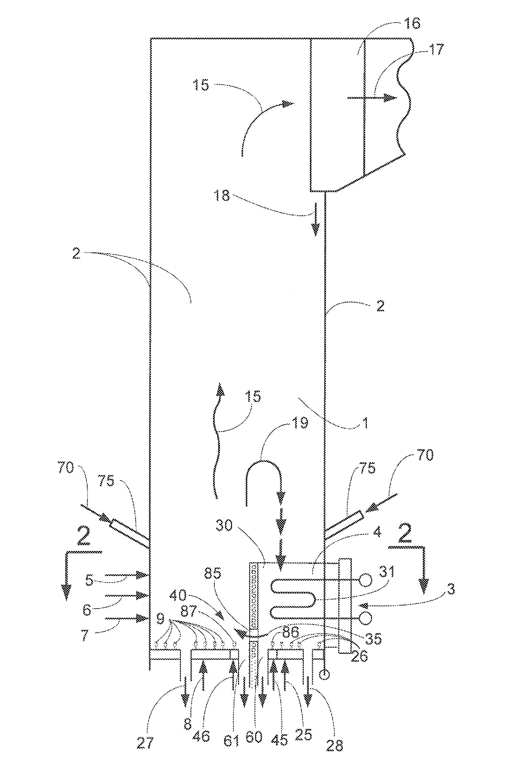
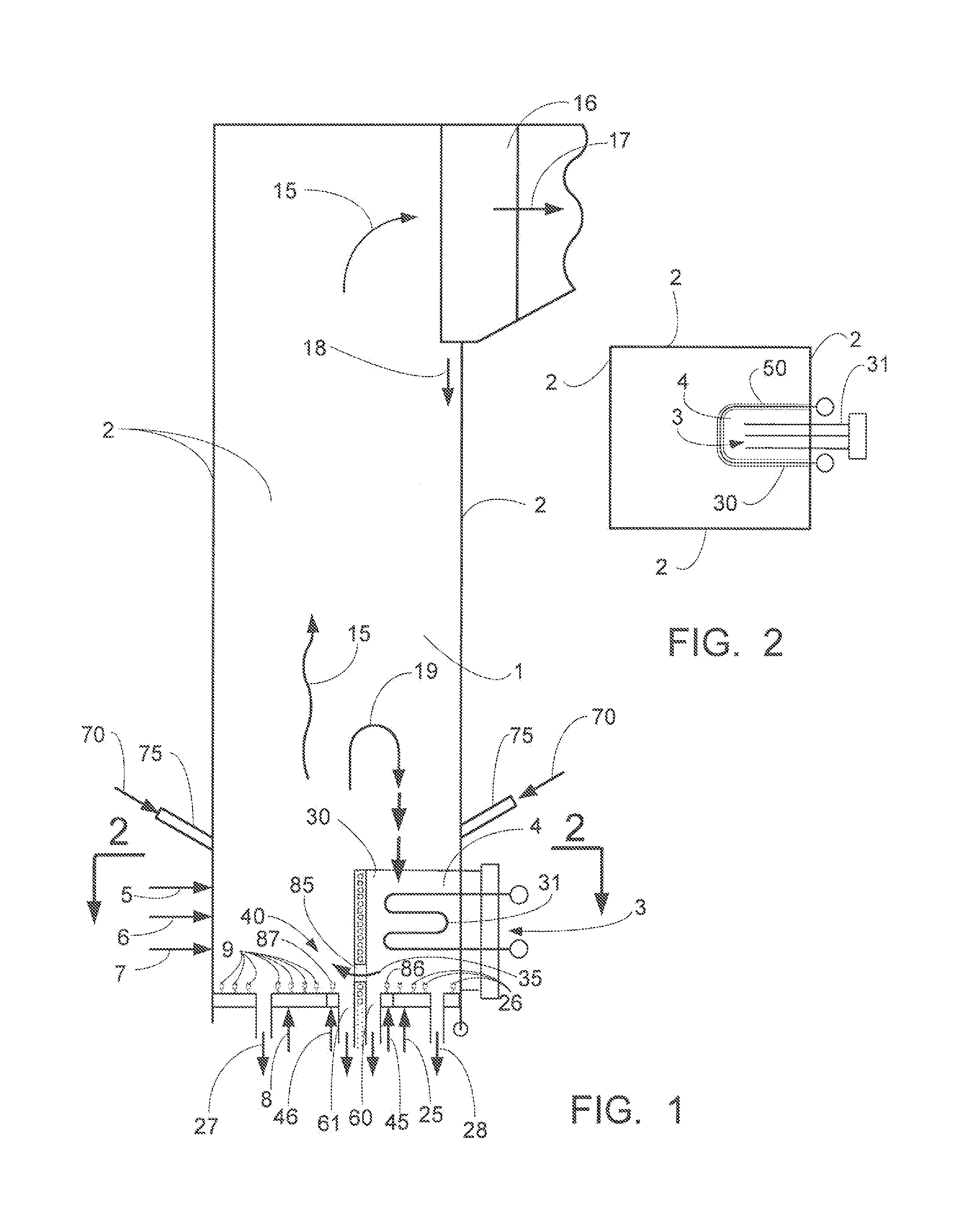
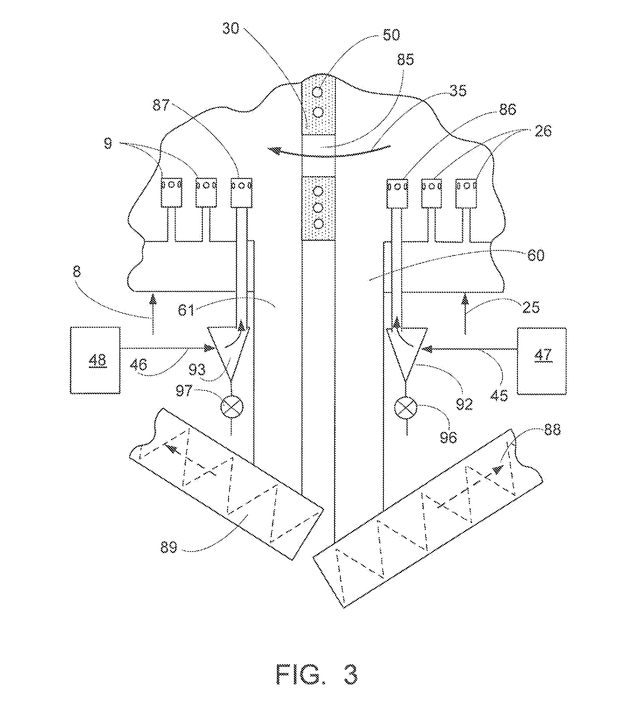
[0028]A more complete understanding of the processes and apparatuses disclosed herein can be obtained by reference to the accompanying drawings. These figures are merely schematic representations based on convenience and the ease of demonstrating the existing art and / or the present development, and are, therefore, not intended to indicate relative size and dimensions of the assemblies or components thereof.

[0029]Although specific terms are used in the following description for the sake of clarity, these terms are intended to refer only to the particular structure of the embodiments selected for illustration in the drawings, and are not intended to define or limit the scope of the disclosure. In the drawings and the following description below, it is to be understood that like numeric designations refer to components of like function.

[0030]The modifier “about” used in connection with a quantity is inclusive of the stated value and has the meaning dictated by the context (for example,...


PUM


Abstract

A non-mechanical valve arrangement for use with circulating fluidized bed (CFB) boilers has a CFB reaction chamber and a bubbling fluidized bed (BFB) within an enclosure in the lower portion of the CFB reaction chamber, the BFB containing an in-bed heat exchanger (IBHX). Solids flowing from the BFB enclosure to the CFB reaction chamber may be controlled using one or more non-mechanical valves. Each non-mechanical valve is independently controlled using independently controlled fluidizing means. The non-mechanical valve has collectors to collect solids backsifting into the fluidizing means of the valve. Agglomerates are removed which could block the valve. Channel walls parallel to the direction of solids flow through the valve opening may be provided to reduce external interference with local fluidization to maintain the proper functionality of the non-mechanical valve.

Description

BACKGROUND[0001]The present invention relates generally to the field of circulating fluidized bed (CFB) reactors and boilers such as those used in electric power generation facilities and industrial facilities. It particularly relates to CFB reactor arrangements containing both a CFB and one or more bubbling fluidized bed(s) (BFB's) feeding materials into a lower portion of the CFB reactor enclosure, and to non-mechanical valves for controlling solids flowing between slow bubbling bed region(s) and highly-fluidized CFB regions.[0002]Reactors and boilers can use CFB's and BFB's together in various arrangements. For example, U.S. Pat. No. 5,533,471 teaches placing the slow BFB below and to the side of the bottom of the faster moving CFB chamber. In U.S. Pat. No. 5,526,775, the slow BFB is above and to the side of the fast CFB. U.S. Pat. No. 5,190,451, to Goldbach, illustrates a CFB chamber having a heat exchanger immersed within a fluidized bed at the lower end of the chamber. U.S. Pa...

Claims


Application Information

Patent Timeline
IPC IPC(8): F23C10/02F22B31/00F23C10/24F23C10/10F23C10/18
CPCF23C10/04F23C10/10F23C10/26F23C10/30F23C2206/102F23C2206/103F23C2900/10008F22B31/0038B01J8/24
Inventor MARYAMCHIK, MIKHAILKRAFT, DAVID L.ALEXANDER, KIPLIN C.FLYNN, THOMAS J.HU, SHENGTENG
Owner THE BABCOCK & WILCOX CO
Why Eureka
Try Eureka