Rigid flexible circuit board with impedance control

a flexible circuit board and impedance control technology, applied in the direction of printed circuit aspects, high frequency circuit adaptations, cross-talk/noise/interference reduction, etc., can solve the problems of signal transmission distortion, signal transmission failure and distortion, transmission of differential mode signals is easily subject to troubles, etc., to eliminate errors and distortions of signal transmission.

Active Publication Date: 2014-04-17
ADVANCED FLEXIBLE CIRCUITS
View PDF5 Cites 18 Cited by
  • Summary
  • Abstract
  • Description
  • Claims
  • Application Information

AI Technical Summary

Benefits of technology

[0011]With the technical solution adopted in the present invention, an impedance control structure is formed on a flexible circuit board of a rigid-flexible circuit board so that the impedance control structure controls the impedance that differential mode signals are transmitted through the flexible circuit board. In this way, errors and distortions of signal transmission can be eliminated in the transmission of high frequency differential mode signals of an electronic device.

Problems solved by technology

The manufacturers generally overlook the significance of impedance control in the transmission of high frequency signals and this often results in failure transmission and distortion of signals.
Particularly, when a flexible circuit board is applied to transmission through differential mode signal lines, due to the material characteristics of the flexible circuit board being flexible and bendable, the transmission of differential mode signal is readily subjected to troubles caused by factors including surrounding environment, the wires themselves, and poor impedance control.

Method used


Image

  • Rigid flexible circuit board with impedance control
  • Rigid flexible circuit board with impedance control
  • Rigid flexible circuit board with impedance control

Examples


first embodiment

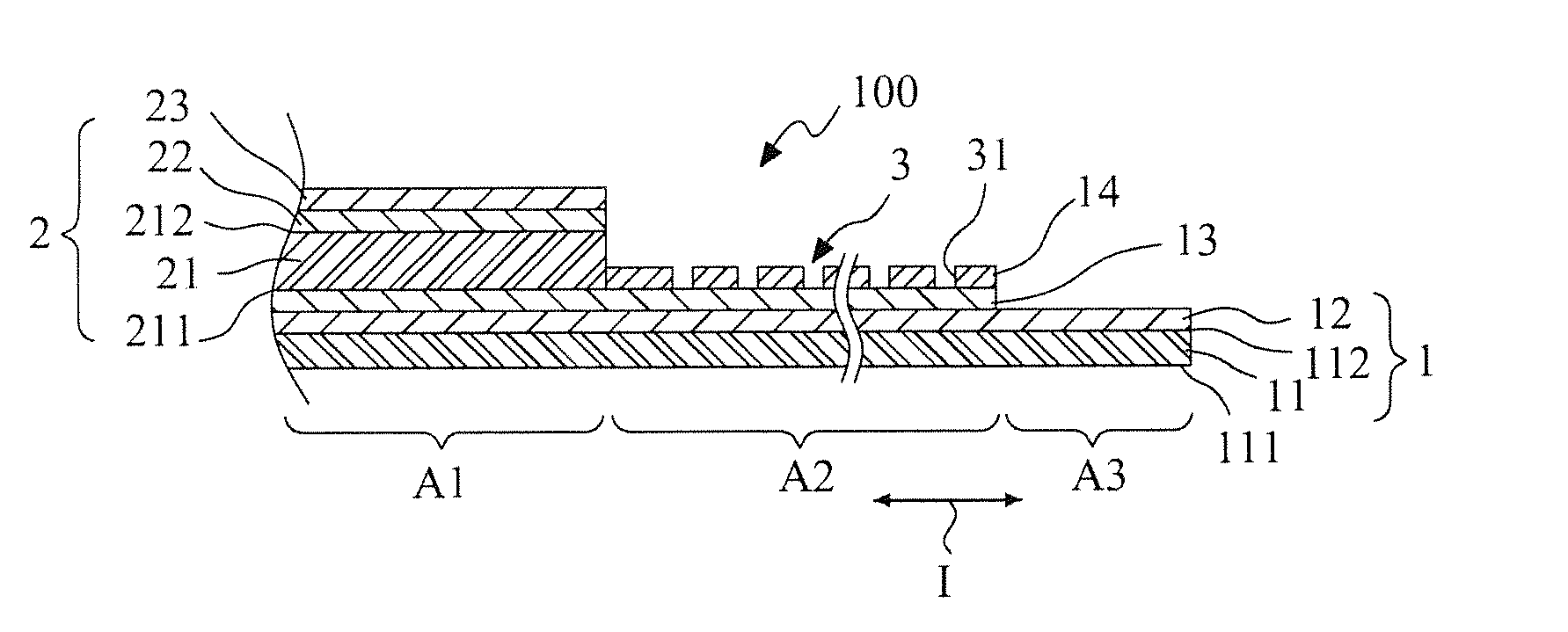
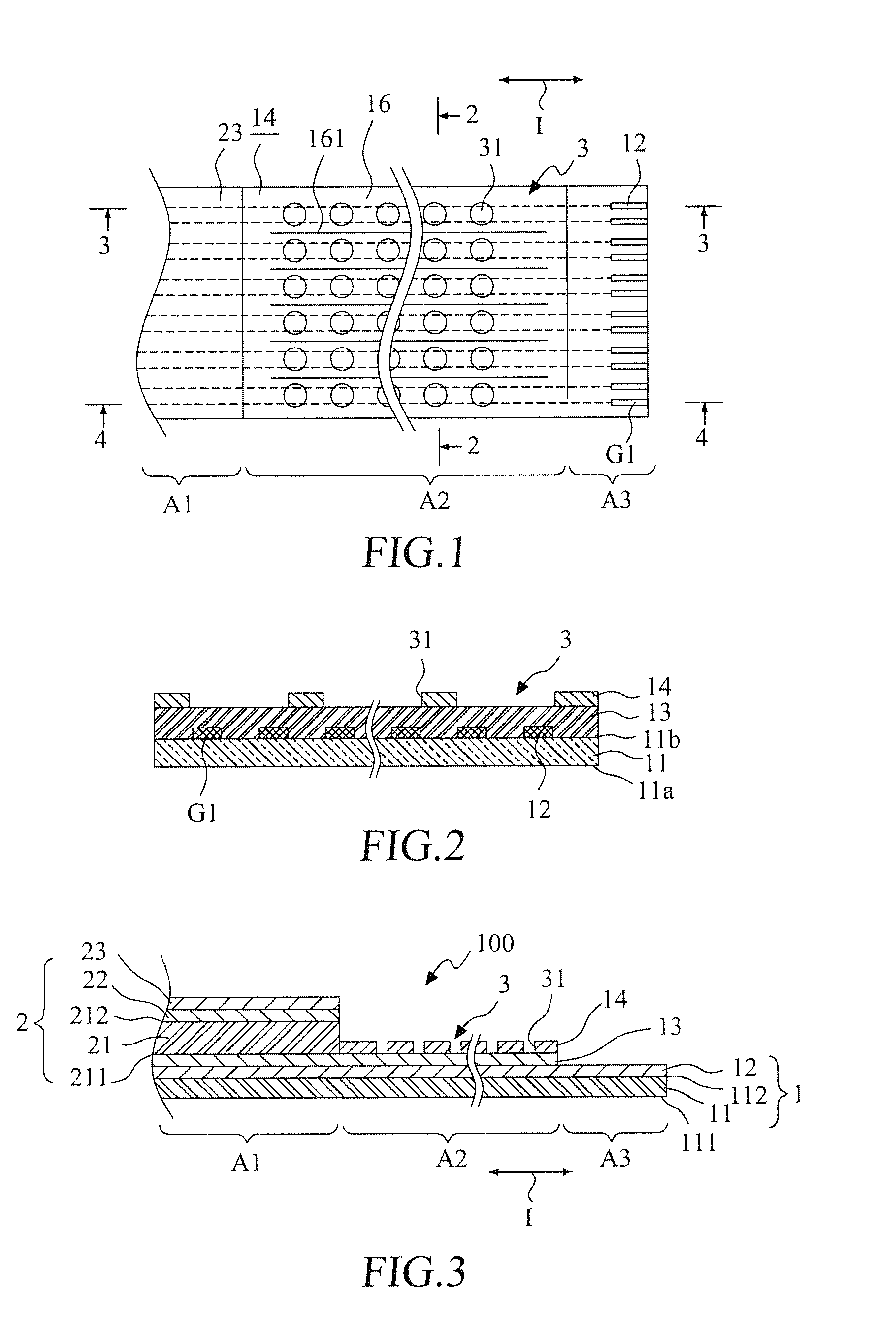
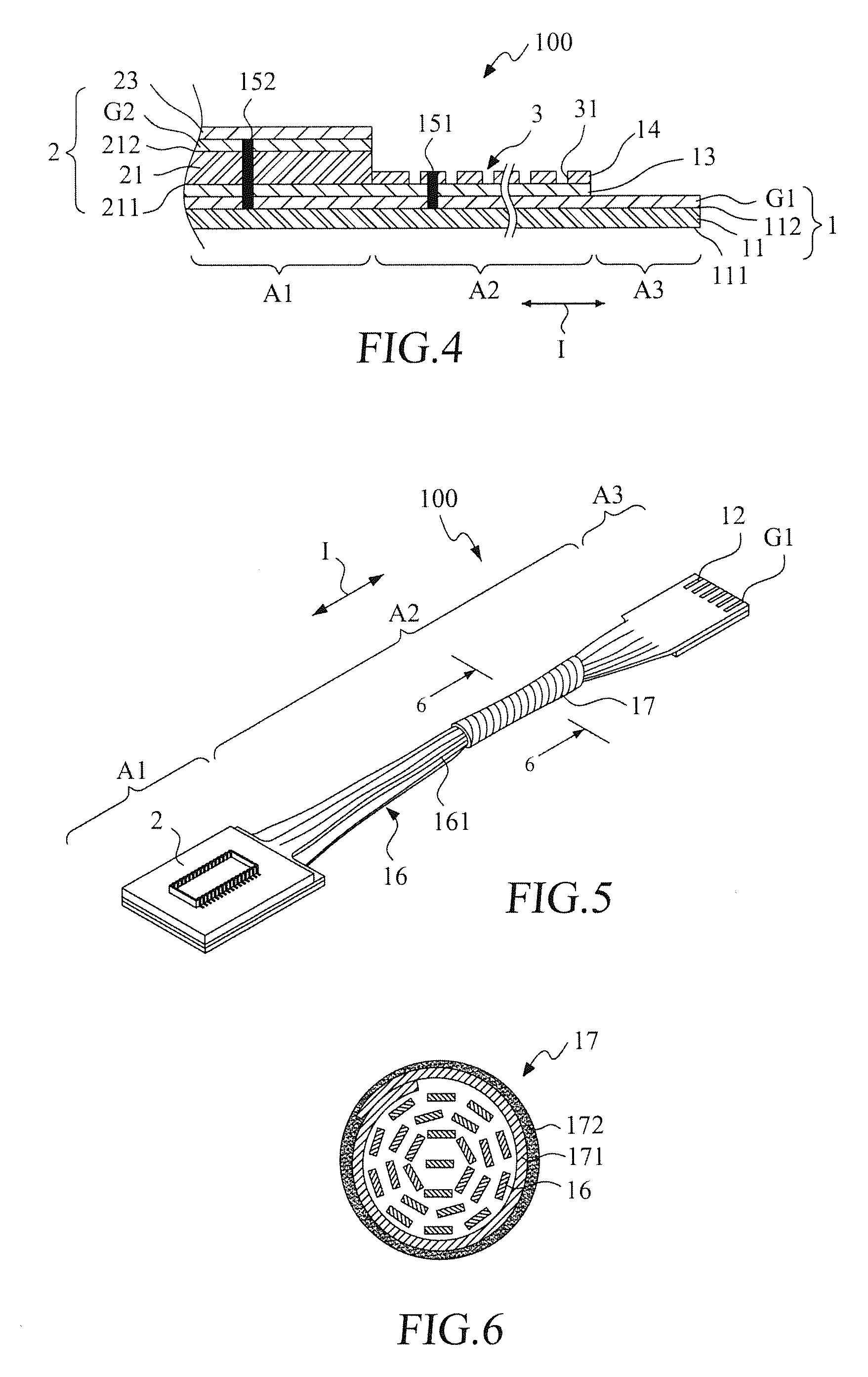
[0028]Referring to FIGS. 1-4, FIG. 1 is a top plan view of the present invention; FIG. 2 is a cross-sectional view of the embodiment of FIG. 1 taken along line 2-2; FIG. 3 is a cross-sectional view taken along lines 3-3 of FIG. 1; and FIG. 4 is a cross-sectional view taken along lines 4-4 of FIG. 1. An impedance control structure included rigid-flexible circuit board according to the present invention, generally designated at 100, comprises a flexible circuit board 1 and a first rigid circuit board 2. The flexible circuit board 1 comprises a flexible-board substrate 11 that extends in an extension direction I and comprises a lower surface 111 and an upper surface 112. The flexible circuit board 1 defines a stacking section A1, an extension section A2, and an exposed conduction section A3 along the extension direction I. The first rigid circuit board 2 corresponds to and is stacked on the stacking section A1. The extension section A2 extends outside an outer end of the stacking secti...

fourth embodiment

[0048]FIG. 9 is a cross-sectional view showing a fourth embodiment according to the present invention. The instant embodiment provides a rigid-flexible circuit board 100c that is an expanded structure formed by modifying the embodiment illustrated in FIG. 8 and comprises, in structure, a first rigid circuit board 2 mounted to the upper surface of the flexible circuit board 1 to correspond to the stacking section A1 and a second rigid circuit board 2a mounted to the lower surface. A third rigid circuit board 2b is mounted to the upper surface of the flexible circuit board 1 at a location (the right-hand side end) opposite to the first rigid circuit board 2 and a fourth rigid circuit board 2c is mounted to the lower surface to correspond to the third rigid circuit board 2b. The fourth rigid circuit board 2c has a structure identical to that of the second rigid circuit board 2a.

fifth embodiment

[0049]FIG. 10 is a cross-sectional view showing a fifth embodiment according to the present invention. A rigid-flexible circuit board 100d according to the instant embodiment has a structure that is an expanded structure formed by modifying the embodiment illustrated in FIG. 4. In the instant embodiment, besides being positioned on the extension section A2, the first shielding layer 141 further extends from the extension section A2 toward the stacking section A1 to be located between the first rigid-board substrate 21 of the first rigid circuit board 2 and the first flexible-board insulation layer 13 of the flexible circuit board 1.


PUM


Abstract

A rigid-flexible circuit board includes at least one flexible circuit board and at least one rigid circuit board. The flexible circuit board includes a flexible-board substrate, a plurality of flexible circuit board differential mode signal lines, at least one flexible circuit board grounding line, a flexible circuit board insulation layer formed on the upper surface of the flexible-board substrate and covering the flexible circuit board differential mode signal lines and the flexible circuit board grounding line. The rigid circuit board is stacked on the stacking section of the flexible circuit board. A shielding layer is formed on the flexible circuit board insulation layer of the flexible circuit board and corresponds to the extension section of the flexible circuit board. The shielding layer further extends from the extension section to the stacking section. An impedance control structure is formed on the shielding layer to control the impedance of the flexible circuit board differential mode signal lines.

Description

BACKGROUND OF THE INVENTION[0001]1. Field of the Invention[0002]The present invention relates to a rigid-flexible circuit board, and in particular to a rigid-flexible circuit board including an impedance control structure.[0003]2. The Related Arts[0004]The vigorous progress of electronic industry makes printed circuit boards playing an important role in taking the place of the conventional ways of arranging flat cables. Further, the development of a flexible printed circuit (FPC) brings a significant upgrade of the electronic industry. The FPC is a technique that a flexible copper foil based substrate is subjected to processing to have wiring directly laid on the substrate. The industry is now continuously devoting themselves to researches and developments of circuit capacity that can be adopted for miniaturization, weight reduction, and dense integration of electronic components of electronic and electrical appliances by increasing the layers of a printed circuit board to form a mu...

Claims


Application Information

Patent Timeline
Patent Type & Authority Applications(United States)
IPC IPC(8): H05K1/02
CPCH05K1/0237H05K1/0218H05K1/0245H05K1/025H05K3/4691H05K2201/09063
Inventor LIN, GWUN-JIN
Owner ADVANCED FLEXIBLE CIRCUITS
Why Eureka
Try Eureka