Image capture device

a multi-view, image technology, applied in the direction of color television details, television system details, television systems, etc., can solve the problem of not being able to effectively reduce the overall volume, and achieve the effect of simple structur

Inactive Publication Date: 2014-04-17
DONGGUAN MASSTOP LIQUID CRYSTAL DISPLAY +1
View PDF7 Cites 136 Cited by
  • Summary
  • Abstract
  • Description
  • Claims
  • Application Information

AI Technical Summary

Benefits of technology

[0007]The present invention is directed to an image capture device, which

Problems solved by technology

A conventional in-vehicle video recorder including a single lens module is only able to take the image within a partial field of view and fails to record a situation of surroundings in an accident.
However, such in-vehicle video recorders are ma

Method used


Image

  • Image capture device
  • Image capture device
  • Image capture device

Examples


first embodiment

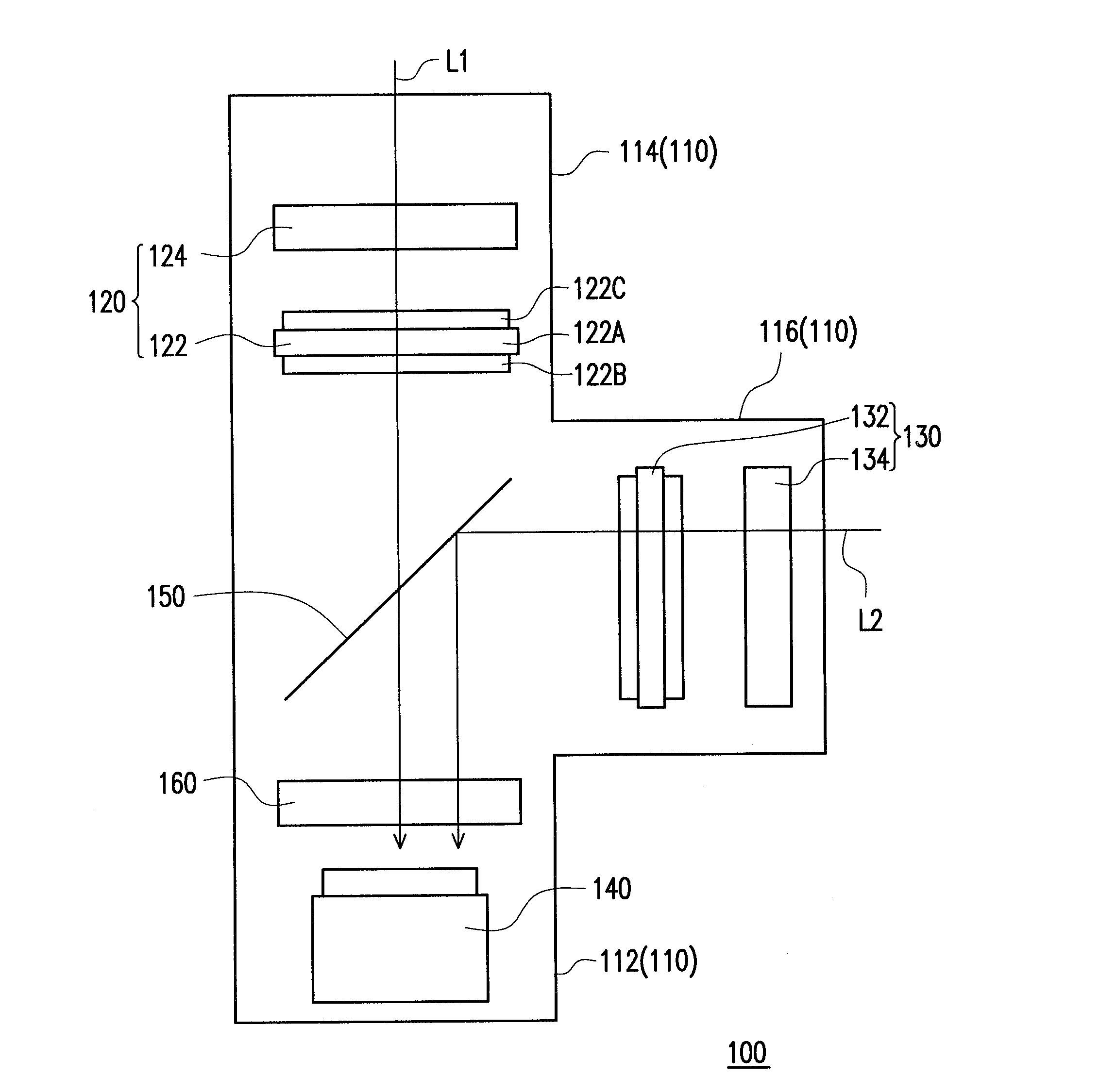
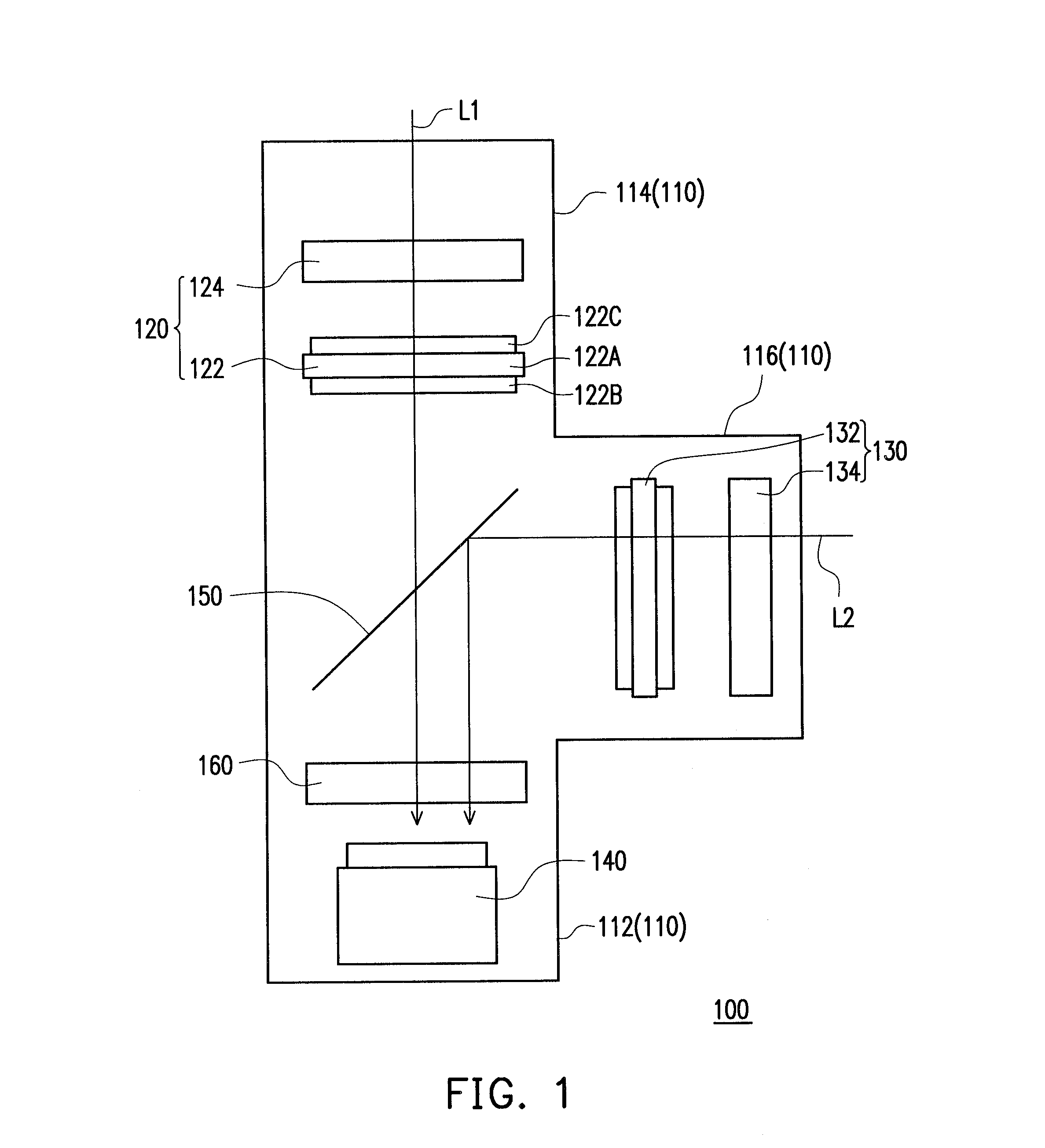
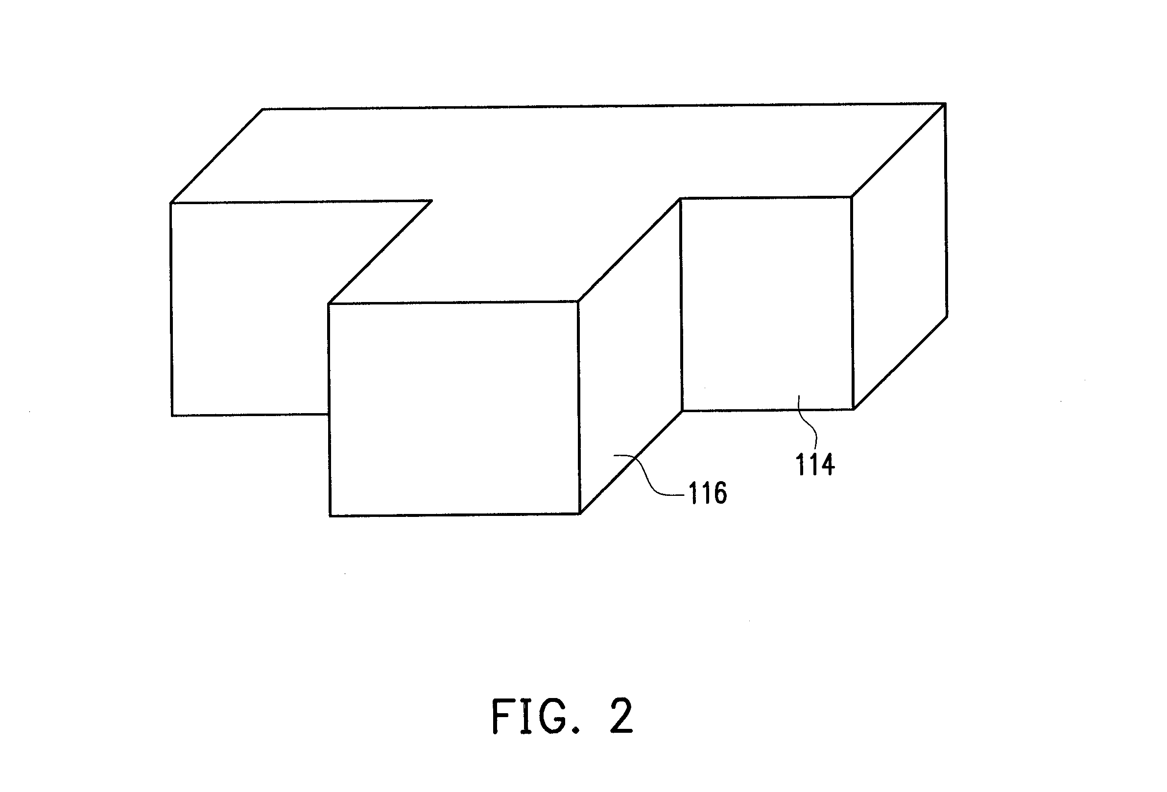
[0030]FIG. 1 is a schematic diagram of an image capture device in accordance with the present invention. FIG. 2 is a schematic diagram of a first lens barrel and a second lens barrel of the image capture device in FIG. 1. Referring to both FIG. 1 and FIG. 2, an image capture device 100 includes a housing 110, a first lens unit 120, a second lens unit 130, an image sensing element 140, a beam spliter 150, and at least one lens 160. The housing 110 includes a body 112, a first lens barrel 114, and a second lens barrel 116. The first lens barrel 114 and the second lens barrel 116 are inter-connected with the body 112. The first lens unit 120 is disposed within the first lens barrel 114 of the housing 110. The second lens unit 130 is disposed within the second lens barrel 116 of the housing 110. The image sensing element 140 is disposed within the body 112. The beam spliter 150 is configured on a light path of a light, in which light will be expectedly received by the image sensing elem...

second embodiment

[0040]The image capture device 100 as hereinbefore is described in a viewpoint of the mutually perpendicular extended directions of the first lens barrel 114 and the second lens barrel 116, and yet the present invention is not limited thereto. For example, FIG. 3A is a schematic diagram of the image capture device in accordance with the present invention, and FIG. 3B is a schematic diagram of the first lens barrel and the second lens barrel of the image capture device in FIG. 3A.

[0041]Referring to both FIG. 3A and FIG. 3B, an image capture device 200 includes a housing 210, a first lens unit 120, a second lens unit 130, an image sensing element 140, a beam spliter 150, at least one lens 160, and a light path adjusting element 270. Concretely speaking, differences between the present embodiment and the first embodiment are mainly from an appearance design of the housing 210 and an arrangement of the light path adjusting element 270. Therefore, structures and arrangement relations of ...

fourth embodiment

[0046]FIG. 5 is a schematic diagram of the image capture device in accordance with the present invention. Referring to FIG. 5, an image capture device 300 substantially includes a housing 310, a first lens unit 320, a second lens unit 330, a third lens unit 340, an image sensing element 350, a beam spliter 360, and at least one lens 370. The housing 310 includes a body 312, a first lens barrel 314, a second lens barrel 316, and a third lens barrel 318. The first lens barrel 314, the second lens barrel 316, and the third lens barrel 316 are all inter-connected with the body 312. The first lens unit 320 is disposed within the first lens barrel 314 of the housing 310. The second lens unit 330 is disposed within the second lens barrel 316 of the housing 310. The third lens unit 340 is disposed within the third lens barrel 318 of the housing 310. The image sensing element 350 is disposed within the body 312. When the image sensing element 350 faces towards the first lens unit 320, the be...


PUM


Abstract

An image capture device including a housing, a first lens unit, a second lens unit, an image sensing element, and a beam spliter is provided. The housing includes a body, a first lens barrel, and a second lens barrel. The first lens unit is disposed within the first lens barrel and includes a first switchable light valve. The second lens unit is disposed within the second lens barrel and includes a second switchable light valve. The image sensing element faces to the first lens unit. The beam spliter is configured in front of the image sensing element so that the image sensing element is able to receive a first image light passing through the first lens unit and a second image light passing through the second lens unit. The first switchable light valve and the second switchable light valve present a transparent state at different timings.

Description

CROSS-REFERENCE TO RELATED APPLICATION[0001]This application claims the priority benefit of Taiwan application serial no. 101137775, filed on Oct. 12, 2012. The entirety of the above-mentioned patent application is hereby incorporated by reference herein and made a part of this specification.BACKGROUND OF THE INVENTION[0002]1. Field of the Invention[0003]The present invention generally relates to an image capture device, in particular, to a multi-view image capture device.[0004]2. Description of Related Art[0005]A conventional in-vehicle video recorder including a single lens module is only able to take the image within a partial field of view and fails to record a situation of surroundings in an accident. Therefore, double lenses are disposed within some new in-vehicle video recorders so as to increase a filming field of view. However, such in-vehicle video recorders are manufactured by a combination of two image capture devices, which are not able to effectively reduce an overall ...

Claims


Application Information

Patent Timeline
IPC IPC(8): H04N5/225
CPCH04N5/2252H04N23/58H04N23/51
Inventor HSIEH, TSUNG-YENCHANG, CHIA-HSIUNG
Owner DONGGUAN MASSTOP LIQUID CRYSTAL DISPLAY
Why Eureka
Try Eureka