Multilayer display apparatus

a multi-layer display and display device technology, applied in the field of multi-layer display devices, can solve the problems of disadvantageous complexness of the apparatus, and achieve the effects of preventing the fluctuation of the angle of convergence or the focal point, and reducing the time it takes to achieve stereoscopic vision

Active Publication Date: 2014-04-17
ALPINE ELECTRONICS INC
View PDF7 Cites 8 Cited by
  • Summary
  • Abstract
  • Description
  • Claims
  • Application Information

AI Technical Summary

Benefits of technology

[0009]A simple configuration in which the two-dimensional display face is simply arranged within a predetermined range of the screen of the stereoscopic vision display device (specifically, coinciding with the position of the screen or in the vicinity of the position of the screen of the stereoscopic vision display device) allows a user to immediately determine a fixation point in the stereoscopic vision display device. Accordingly, the orientation of the stereoscopic vision is stabilized while preventing an angle of convergence or a focal point from fluctuating, and a situation in which the user cannot accommodate properly due to a mismatch between convergence and accommodation can be prevented. Thus, the time it takes to achieve stereoscopic vision can be reduced, and 3D sickness can also be reduced.
[0010]Further, it is preferable that the aforementioned two-dimensional image be a visually useful and attractive image. Specifically, it is preferable that the screen of the stereoscopic vision display device and the two-dimensional display face be arranged in front of a driver's seat of a vehicle and that the visually useful and attractive image be an image representing an instrument associated with driving the vehicle. Here, it is preferable that the stated instrument be at least one of a speedometer and a tachometer. In addition, it is preferable that the aforementioned visually attractive image be at least one of an image with higher luminance, an image with higher contrast, an image with higher color saturation, an image with a more prominent hue, and a more dynamic image compared to the three-dimensional image. Such an image gives a visually strong impression on the user and thus is suitable as a fixation point in the stereoscopic vision display device. Thus, the time it takes to achieve stereoscopic vision can be further reduced.
[0011]Furthermore, it is preferable that the aforementioned stereoscopic vision display device be configured to display the three-dimensional image through a parallax barrier method or a lenticular method. Using such a technique in the stereoscopic vision display device makes it possible to further simplify the configuration thereof.
[0012]It is preferable that the multilayer display device further include a half-silvered mirror arranged between the screen of the stereoscopic vision display device and the user's eyes so as to be inclined relative to the line of sight of the user and that a virtual image formed in the two-dimensional display device using the half-silvered mirror be used as the two-dimensional image. Specifically, it is preferable that the virtual image be superimposed on the screen of the aforementioned stereoscopic vision display device. Generating the two-dimensional image using the virtual image formed through the half-silvered mirror makes it possible to dispose the two-dimensional display device at a position spaced apart from the stereoscopic vision display device, and thus the details of the multilayer display apparatus can be prevented from becoming complex.
[0013]Furthermore, it is preferable that at least part of the three-dimensional image be displayed on the screen of the aforementioned stereoscopic vision display device in a region other than a region where the two-dimensional image is displayed. Through such a configuration, a display region in the stereoscopic vision display device can be secured, and a fixation point in the stereoscopic vision display device can be determined with ease.

Problems solved by technology

However, a focusing system array or a large-aperture focusing system needs to be provided between the display face and a viewer, and thus the apparatus is disadvantageously complex.

Method used


Image

  • Multilayer display apparatus
  • Multilayer display apparatus
  • Multilayer display apparatus

Examples


Embodiment Construction

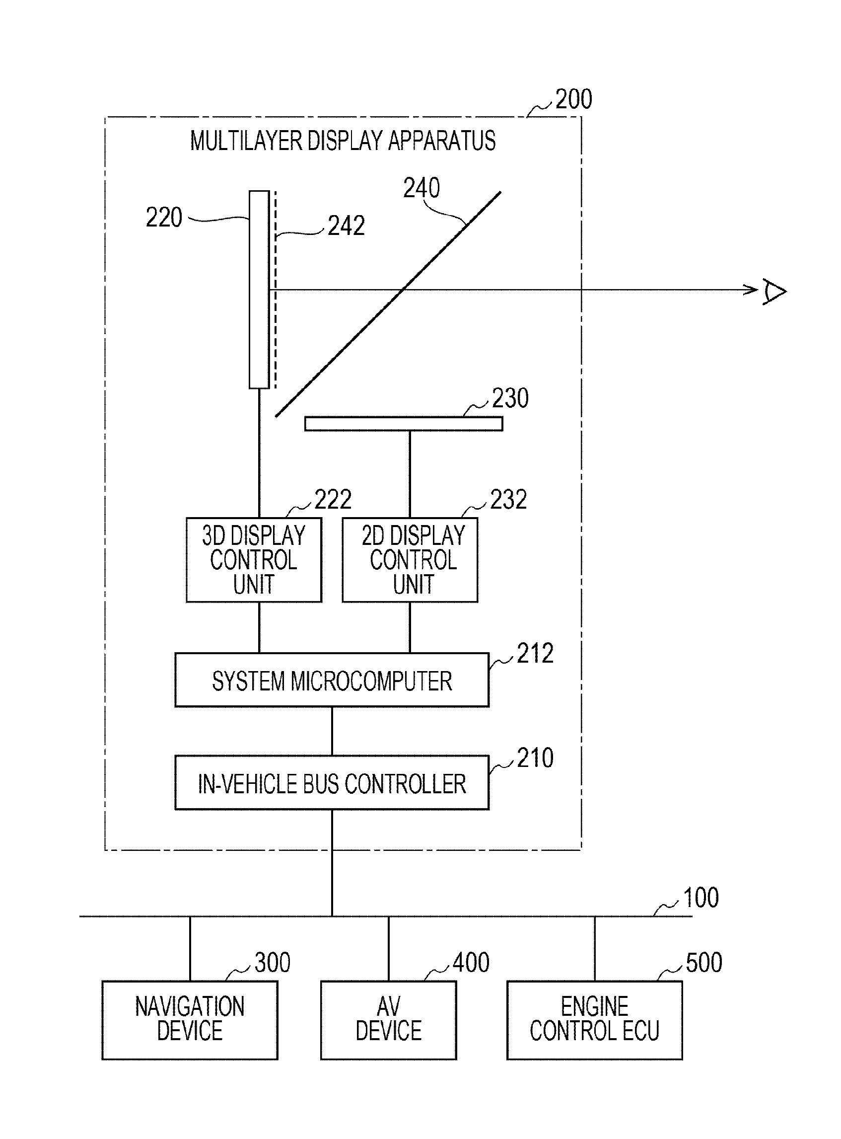
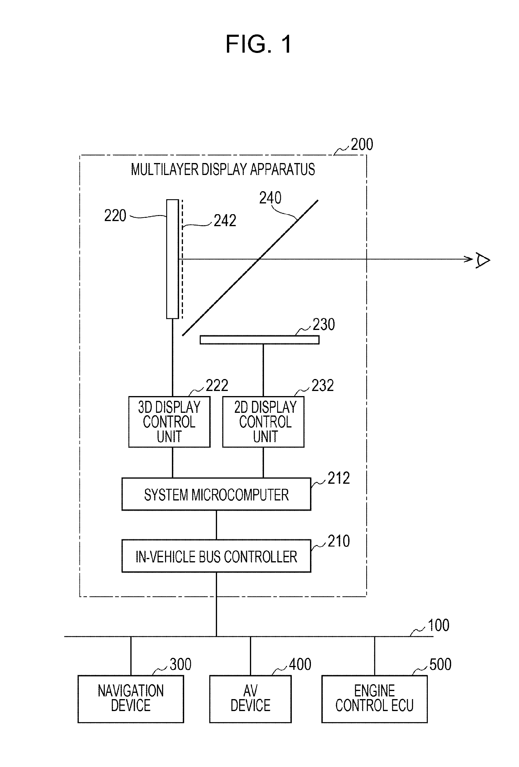
[0020]Hereinafter, an in-vehicle system of an embodiment to which the present invention is applied will be described with reference to the drawings. FIG. 1 illustrates a configuration of the in-vehicle system of the embodiment. As illustrated in FIG. 1, the in-vehicle system of the present embodiment includes a multilayer display apparatus 200, a navigation device 300, an audiovisual (AV) device 400, and an engine control ECU (electronic control unit) 500, which are interconnected through an in-vehicle bus 100. The in-vehicle bus 100, for example, transmits and receives signals in accordance with a controller area network (CAN) protocol. Note that an in-vehicle bus that is compatible with a protocol other than the CAN protocol may instead be used.

[0021]The multilayer display apparatus 200 displays various pieces of information that are necessary while driving on a display unit disposed in front of the driver's seat of the vehicle. The multilayer display apparatus 200 includes an in-...


PUM


Abstract

A multilayer display apparatus included in an in-vehicle system includes a stereoscopic vision display device formed by a 3D display unit and a 3D display control unit that display a three-dimensional image utilizing the principle of binocular disparity, a two-dimensional display device formed by a 2D display unit and a 2D display control unit that display a two-dimensional image on a two-dimensional display face, and a half-silvered mirror. The position of the two-dimensional display face is set within a predetermine range of the position of the screen of the stereoscopic vision display device by using the half-silvered mirror.

Description

PRIORITY CLAIM[0001]This application claims the benefit of Japanese Patent Application No. 2012-229106 filed on Oct. 16, 2012, and which is incorporated by reference herein in its entirety.BACKGROUND[0002]1. Field of the Invention[0003]The present invention relates to a multilayer display apparatus configured to display stereoscopic vision images utilizing binocular disparity techniques.[0004]2. Description of the Related Art[0005]To date, a multi-viewpoint stereoscopic display apparatus is known that includes a plurality of display devices for providing multilayered background edges on faces other than a stereoscopic vision display face. In such a multi-viewpoint stereoscopic display apparatus, a feeling of space is obtained by a stereoscopic vision display device, and a video image having a high spatial frequency around an edge portion is subjected to a multilayer display by matching the convergence and accommodation position with a focal position (see, for example, Japanese Unexa...

Claims


Application Information

Patent Timeline
Patent Type & Authority Applications(United States)
IPC IPC(8): G02B27/22G02B30/27G02B30/30
CPCG02B27/225G02B27/2214G02B30/27G02B30/30
Inventor NAGAHARA, OSAMU
Owner ALPINE ELECTRONICS INC
Why Eureka
Try Eureka