Switching Device And A Switchgear

a switchgear and switch technology, applied in earthing switches, substations, non-enclosed substations, etc., can solve the problems that prior art switchgears may require too much space in order to meet safety regulations, and achieve stable switching device and system, efficient control of breaker, and efficient support

Inactive Publication Date: 2014-04-17
ABB TECH AG
View PDF3 Cites 18 Cited by
  • Summary
  • Abstract
  • Description
  • Claims
  • Application Information

AI Technical Summary

Benefits of technology

[0043]According to a further advantageous embodiment of the switching device according to the present invention, the outer surface of the housing is smoothly curved towards and into the through-hole. By means of this embodiment, a so called triple point with high dielectric stress may be avoided. This is advantageous when using a shaft which is inserted into the through-hole.
[0044]According to another advantageous embodiment of the switching device according to the present invention, the switching device comprises a shaft inserted into the through-hole of the housing, wherein the shaft is rotatable about its longitudinal axis and in relation to the housing, wherein the shaft is connected to the at least one guiding member, and wherein the shaft and its rotation is adapted to control the movement of the at least one guiding member. By means of this embodiment, an efficient control of the breaker is provided, which does not impair the distribution of the electric field to any substantial extent. Advantageously, when each of a plurality of phases, e.g. three phases, is provided with the innovative switching device, the same shaft may be inserted into the through-hole of each housing to control the movement of the at least one guiding member of all the housings. Alternatively, instead of using said shaft to operate the breaker, two pulling / pushing rods may be used, one for opening the breaker and one for closing the breaker. Other means for controlling the breaker are also possible.
[0045]According to still another advantageous embodiment of the switching device according to the present invention, the housing is made of at least one casted part. Advantageously, the housing can be made of two casted parts which are joined by suitable means. By means of these embodiments, the breaker will be efficiently supported, and a mechanically stable switching device and system are attained.
[0046]According to yet another advantageous embodiment of the switching device according to the present invention, the housing has a smooth outer shape to distribute the electric field generated by the voltage of the current through the switching device. The outer shape, or the outer geometry, of the housing is smooth in that the housing does not have an angular outer shape, e.g. with sharp corners or edges, and is without roughness. By this embodiment, the electric field, or electric field stress, generated by the voltage of the current through the switching device is further evenly distributed in an efficient way, and the risk of flashover, discharges or arcing between the components of the switching device and between the housing and the surroundings, e.g. the housing of a switching device of another phase, or ground, is further reduced. As a result, the switchgear provided with one or a plurality of the switching devices according to the present invention can be made more compact and less bulky, and less space for the switchgear is needed. Further, any additional shielding of the electric field is avoided.
[0047]According to an advantageous embodiment of the switching device according to the present invention, the housing has an outer surface which is smooth to distribute the electric field generated by the voltage of the current through the switching device. The outer surface of the housing is smooth in that the outer surface has no roughness, projections or sharp indentations. The outer surface is evenly curved. By means of this embodiment, the even distribution of the electric field, or electric field stress, is further improved. The risk of flashover, discharges or arcing between components or units of a switchgear is further reduced, and the switchgear can have a more compact design.
[0048]The above-mentioned objects of the present invention are also attained by providing a switchgear for electric power distribution, wherein the switchgear comprises at least one switching device as provided in the claims, and / or at least one switching device according to any of the above-mentioned embodiments of the switching device. By means of the switchgear according to the present invention, a switchgear having both a compact design and a reduced risk of flashover, discharges or arcing between components or units of a switchgear is attained. Otherwise, an improved switchgear is provided for reasons stated above in connection with the disclosure of the various embodiments of the switching device according to the present invention.

Problems solved by technology

Prior art switchgears may require too much space in order to fulfil safety regulations, i.e. in order to prevent the occurrence of discharges or arcs.

Method used


Image

  • Switching Device And A Switchgear
  • Switching Device And A Switchgear
  • Switching Device And A Switchgear

Examples


Embodiment Construction

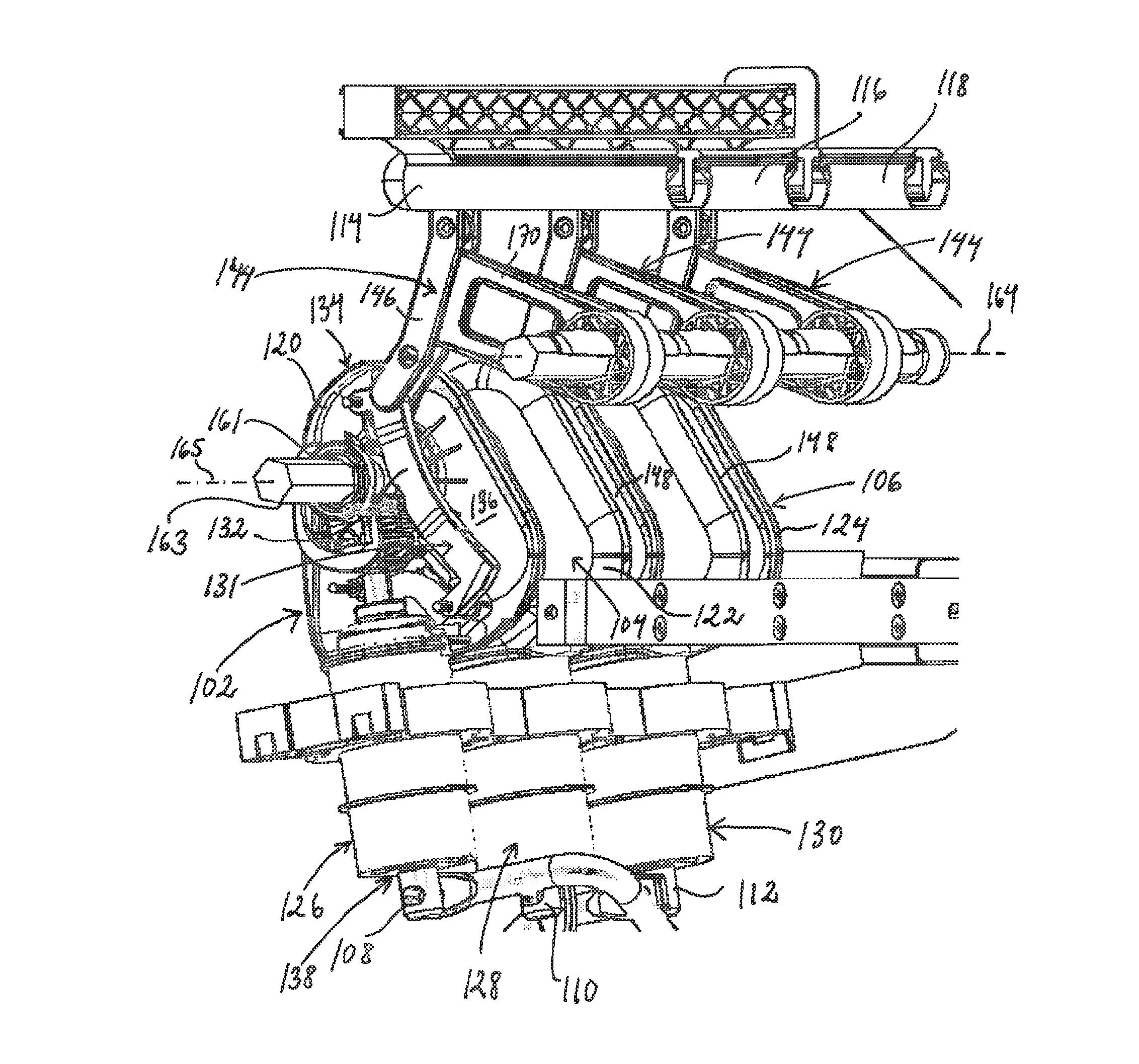
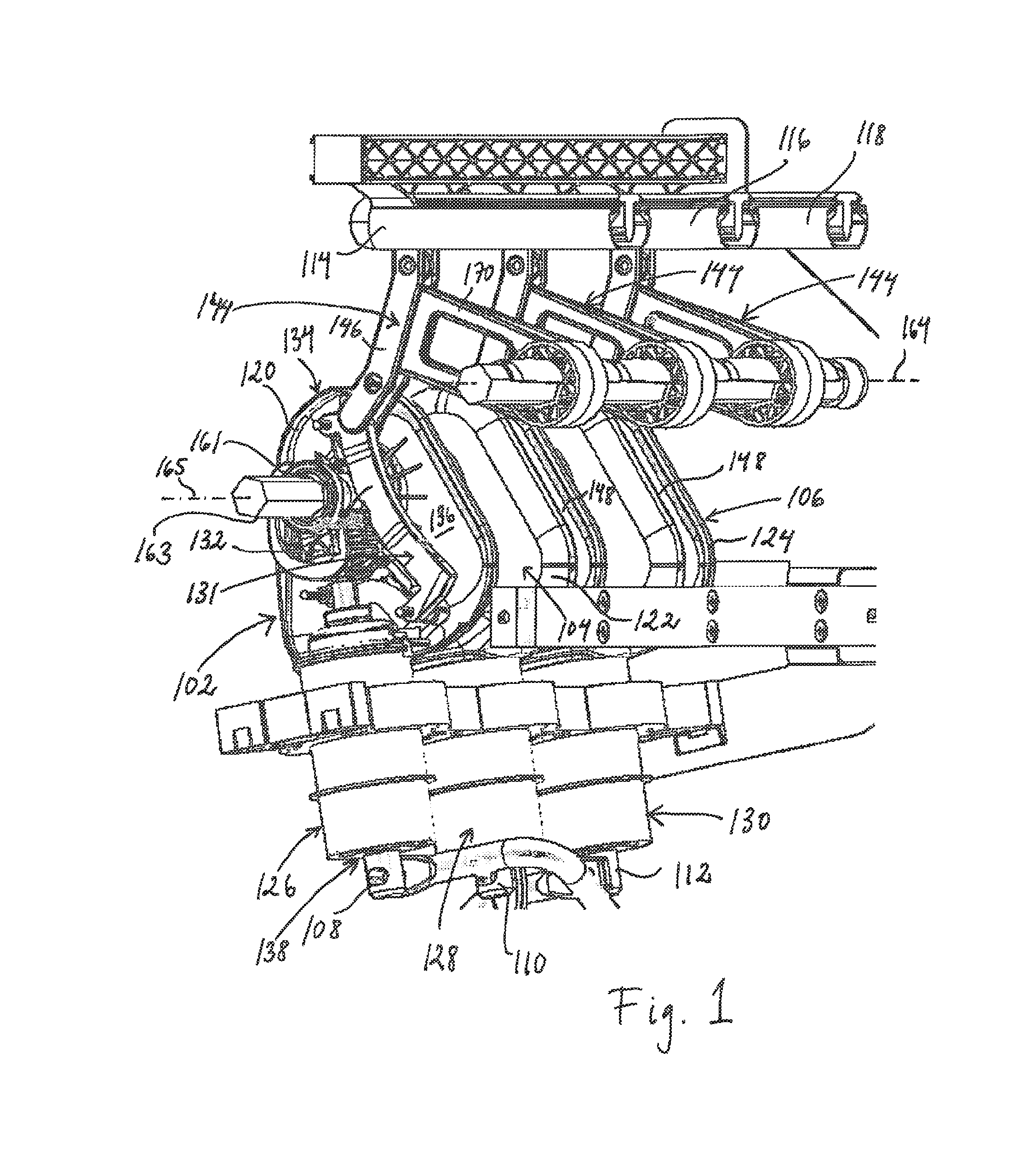
[0061]FIG. 1 schematically shows an embodiment of the switchgear according to the present having three embodiments of the switching device 102, 104, 106 for electric power distribution according to the present invention, where one of the switching devices 102 has a part of the housing cut away for illustrative purposes. The shown switchgear is an electric power distribution switchgear and comprises a plurality of switching devices 102, 104, 106 which can be housed in an encapsulation 107 (see FIG. 5). The encapsulation 107 may be penetrated by a number of electrical bushings (not shown), one for each phase of a plural phase system. From each electrical bushing, a respective conducting element 108, 110, 112 may extend to the respective switching device 102, 104, 106. On the outside of the encapsulation 107, the electrical bushings may be connected to cables (not shown) which either connect the switchgear to a load or to a medium or high voltage power distribution line.

[0062]Each swit...


PUM


Abstract

A switching device for electric power distribution, includes a breaker that is electrically connectable to a conductor, and an electrically conductive housing to which the breaker is mounted. The device provides a current path between the breaker and the conductor. The housing houses at least one guiding member for operating the breaker and a first part of the current path, the first part being electrically connected to the breaker. The device also includes a switch for electrically connecting the breaker to the conductor, the switch having a switch element movable to a first position where the switch element is connected to the first part and the conductor, movable to a second position where the switch element is disconnected from the conductor and connected to the first part and a grounded element, and movable to a third position where the switch element is disconnected from the conductor and the grounded element.

Description

FIELD OF THE INVENTION[0001]The present invention relates to a switching device for electric power distribution, that is electrically connectable to an electrical conductor. The switching device comprises a breaker, which is electrically connectable to the electrical conductor, and a housing to which the breaker is mounted, wherein the housing is at least partially electrically conductive. The switching device provides a current path between the breaker and the electrical conductor. The housing houses at least one guiding member for operating the breaker, the at least one guiding member being movable in relation to the housing. The housing houses a first part of the current path between the breaker and the electrical conductor, the first part of the current path being electrically connected to the breaker. The housing also has an outer surface. Further, the present invention relates to a switchgear comprising at least one switching device of the above-mentioned sort.BACKGROUND OF TH...

Claims


Application Information

Patent Timeline
Patent Type & Authority Applications(United States)
IPC IPC(8): H02B5/00
CPCH02B5/00H01H31/003H01H33/126H01H33/6661
Inventor BJORTUFT, TOM-RUNEENDRE, THORSKRYTEN, PAAL KRISTIANHADLAND, HAVARDTVETEN, JOHN-ANDERSLOHNE, STANLEY
Owner ABB TECH AG
Why Eureka
Try Eureka