3D printing shrinkage compensation using radial and angular layer perimeter point information

a 3d printing and perimeter point technology, applied in the field of additive layer 3d printing, can solve the problems of shape shrinkage and hence shape inaccuracy, dimensional accuracy control can remain a bottleneck, and the fea method may be limited by inadequate physical understanding, so as to minimize errors and minimize errors. the effect of the effect of the effect of the error

Active Publication Date: 2014-04-17
UNIV OF SOUTHERN CALIFORNIA
View PDF1 Cites 105 Cited by
  • Summary
  • Abstract
  • Description
  • Claims
  • Application Information

AI Technical Summary

Benefits of technology

[0016]A data processing system may minimize errors caused by material phase change shrinkage during additive layer 3D printing. Information indicative of the shape of a layer of a 3D object that is to be printed may be received. A shape that most closely corresponds to the shape of the layer may be selected from a library of shapes. Each shape in the library may have shrinkage information associated with it that includes, for each of multiple points that define a perimeter of the library shape, a radial distance to the point from an origin of a coordinate system, an angle the radial distance makes with respect to an axis of the coordinate sy...

Problems solved by technology

Despite these promising features, dimensional accuracy control can remain a bottleneck for application of 3D printing in direct manufacturing.
Material solidification can be involved during layer formation, and this phase change from liquid to solid can lead to shape shrinkage and hence shape inaccuracy.
However, the FEA method may be limited by inadequate physical understanding, and a trade-off between accuracy and computational complexity.
In addition, a large number of model parameters can be difficult to acquire accurately in practice and model complexity can reduce its practicality in direct and efficient control of shape accuracy.
However this approach may only control or reduce average shape shrinkage.
However, prediction of deformation based on the shift of individual points can be independent of the geometry of the product, which may not be consistent with the physical manufacturing process.
However, the position of AM light exposure may not play the same dominant role as the tool tip position of CNC machines.
As previously mentioned, part geometry and shape, process planning, materials, and processing techniques jointly can have complex effects on the profile ...

Method used


Image

  • 3D printing shrinkage compensation using radial and angular layer perimeter point information
  • 3D printing shrinkage compensation using radial and angular layer perimeter point information
  • 3D printing shrinkage compensation using radial and angular layer perimeter point information

Examples


Embodiment Construction

[0045]Illustrative embodiments are now described. Other embodiments may be used in addition or instead. Details that may be apparent or unnecessary may be omitted to save space or for a more effective presentation. Some embodiments may be practiced with additional components or steps and / or without all of the components or steps that are described.

Overview

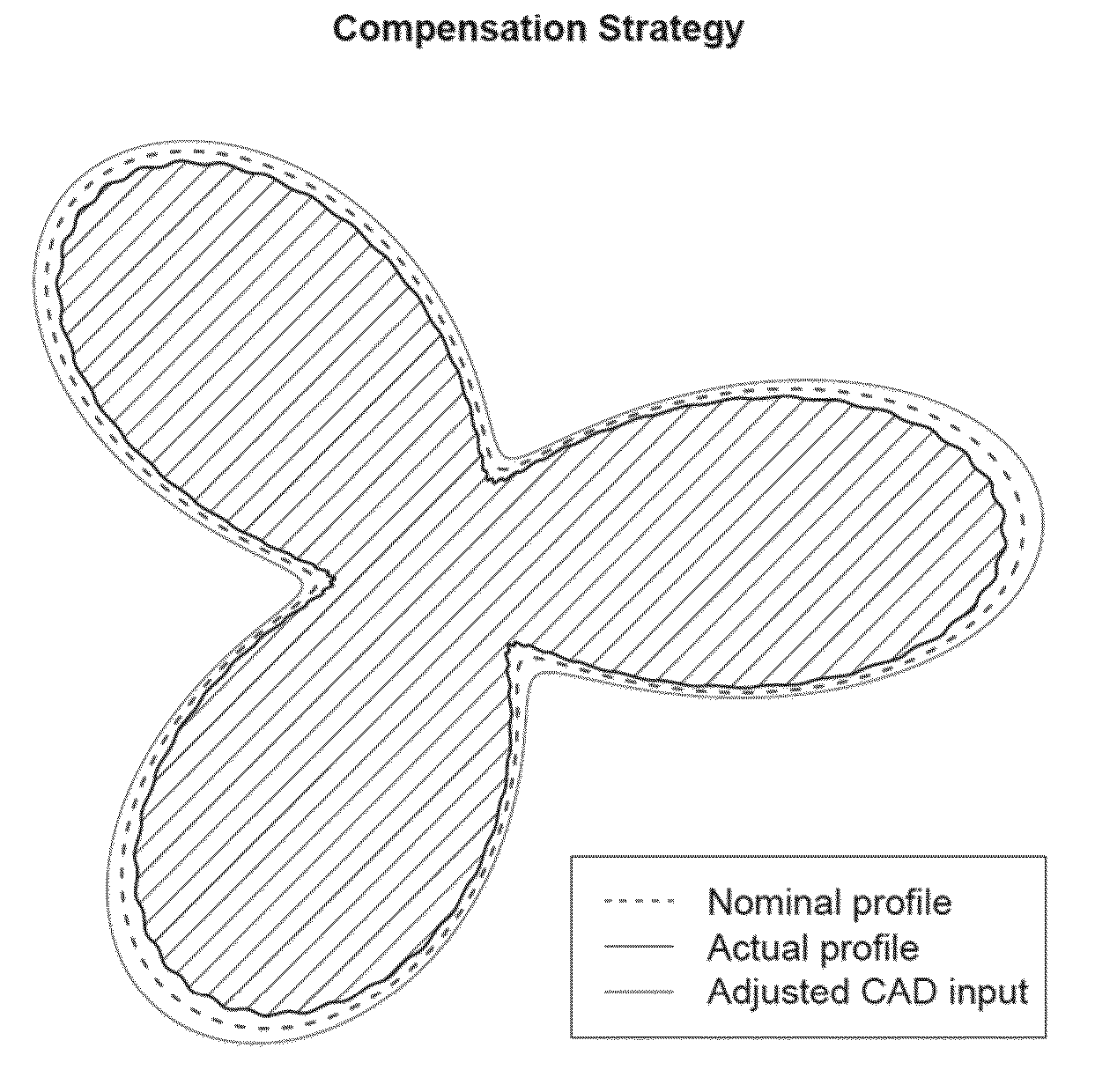
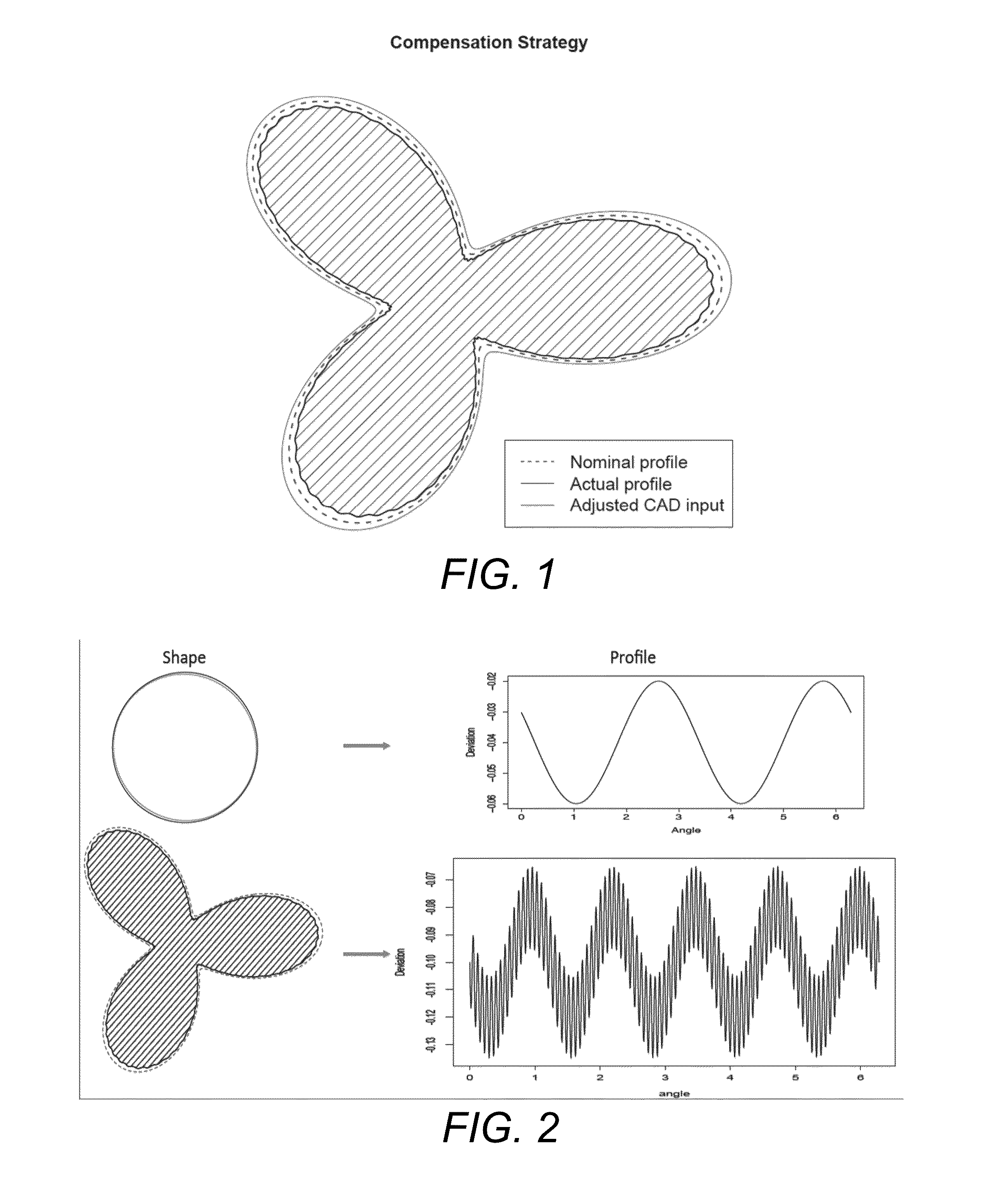
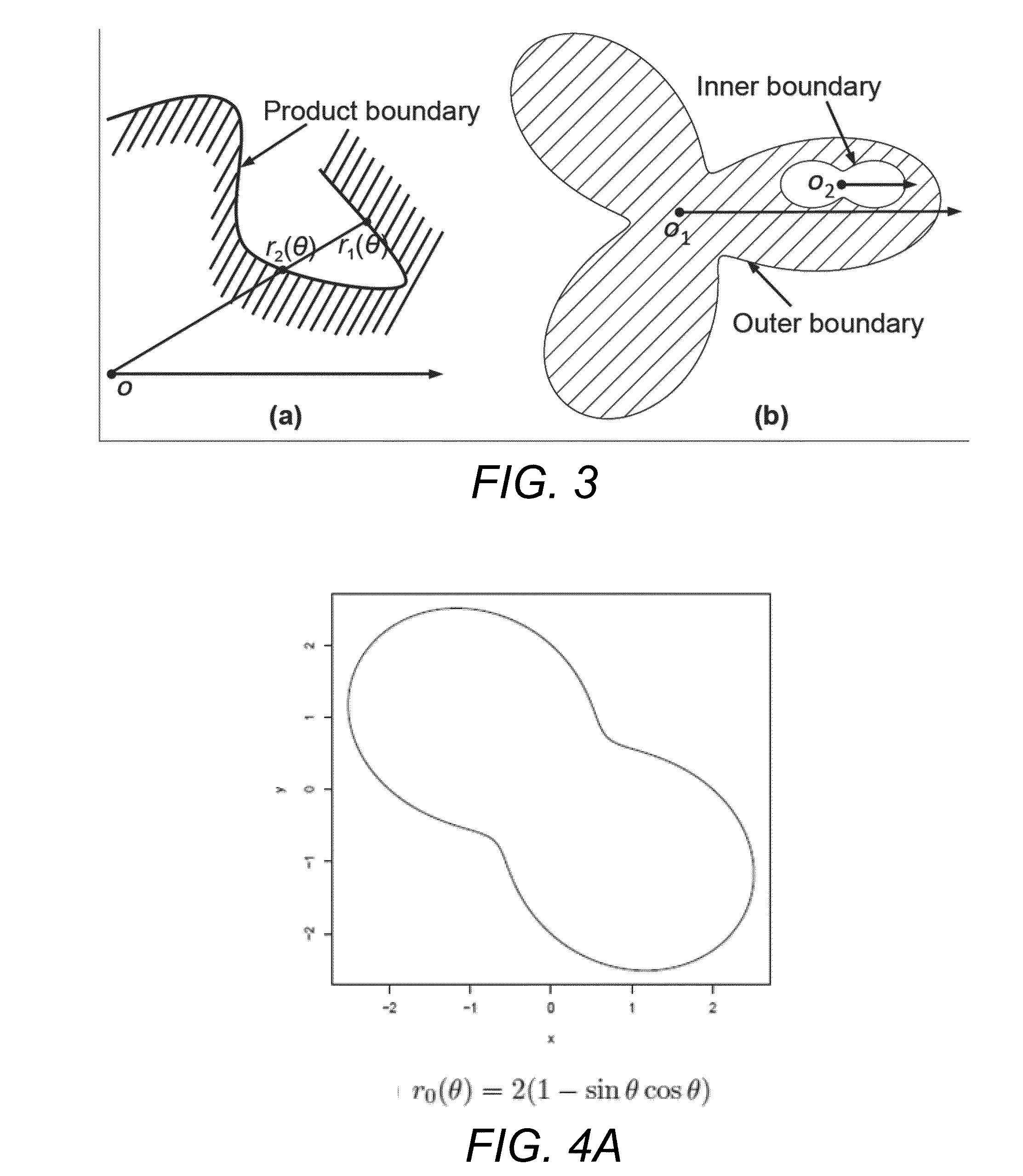
[0046]Systematic models for accuracy control through shrinkage compensation are now described. The approach may: (1) model and predict part shrinkage, and (2) derive an optimal shrinkage compensation plan to achieve dimensional accuracy. The approach has been demonstrated both analytically and experimentally in a stereo-lithography process, a widely employed 3D printing technique. Experimental results demonstrate the ability of the compensation approach to achieve an improvement of one order of magnitude in reduction of geometric errors for cylindrical products.

[0047]A shape error control strategy that may be applicable to both cal...


PUM

PropertyMeasurementUnit
Angleaaaaaaaaaa
Shrinkageaaaaaaaaaa
Shapeaaaaaaaaaa

Abstract

Errors caused by shrinkage during 3D printing may be minimized. A shape that most closely corresponds to the shape of a layer to be printed may be selected from a library of shapes. Each shape in the library may have shrinkage information associated with it that includes, for each of multiple points that define a perimeter of the library shape, a radial distance to the point from an origin of a coordinate system, an angle the radial distance makes with respect to an axis of the coordinate system, and information indicative of an anticipated amount by which the point will deviate from its specified location when the shape is printed due to shrinkage. Compensation for anticipated shrinkage may be calculated based on the shrinkage information that is associated with the selected shape from the library. The information indicative of the shape of the layer to be printed may be modified to minimize errors cause by shrinkage based on the calculated compensation.

Description

CROSS-REFERENCE TO RELATED APPLICATION[0001]This application is based upon and claims priority to U.S. provisional patent application 61 / 712,723, entitled “Algorithm of Compensating Shape Shrinkage for 3D Printing Processes,” filed Oct. 11, 2012, attorney docket number 028080-0799. The entire content of this application is incorporated herein by reference.STATEMENT REGARDING FEDERALLY SPONSORED RESEARCH[0002]This invention was made with government support under Grant No. N00014-1110671, awarded by the Office of Naval Research. The government has certain rights in the invention.BACKGROUND[0003]1. Technical Field[0004]This disclosure relates to additive layer 3D printing, including compensating for errors caused by shrinkage during material phase changes.[0005]2. Description of Related Art[0006]Additive manufacturing, or 3D printing, refers to a class of technologies for the direct fabrication of physical products from a 3D CAD model by a layered manufacturing process. In contrast to ...

Claims


Application Information

Patent Timeline
IPC IPC(8): G06F17/50B22F3/00B29C67/00
CPCG06F17/50B22F3/008B29C67/0088B29C64/112C21B2400/052B29C64/393Y02P10/25B22F10/85B22F10/12G06F30/00
Inventor HUANG, QIANG
Owner UNIV OF SOUTHERN CALIFORNIA
Why Eureka
Try Eureka