Cooling system

a cooling system and cooling technology, applied in heat pumps, lighting and heating apparatus, transportation and packaging, etc., can solve the problems of reducing the cooling performance of the vehicle, reducing the cooling efficiency of the vehicle, and increasing so as to reduce the power consumption of the compressor and reliably cool the heat generating source.

Inactive Publication Date: 2014-04-24
TOYOTA JIDOSHA KK
View PDF10 Cites 10 Cited by
  • Summary
  • Abstract
  • Description
  • Claims
  • Application Information

AI Technical Summary

Benefits of technology

[0014]With the cooling system according to the aspect of the invention, it is possible to reliably cool a heat gener

Problems solved by technology

Therefore, there is a problem that the power consumption of the compressor increases and the fuel economy of the vehicle deteriorates.
In addition, the heat exchanger that exchanges heat with the heat ge

Method used


Image

  • Cooling system
  • Cooling system
  • Cooling system

Examples


first embodiment

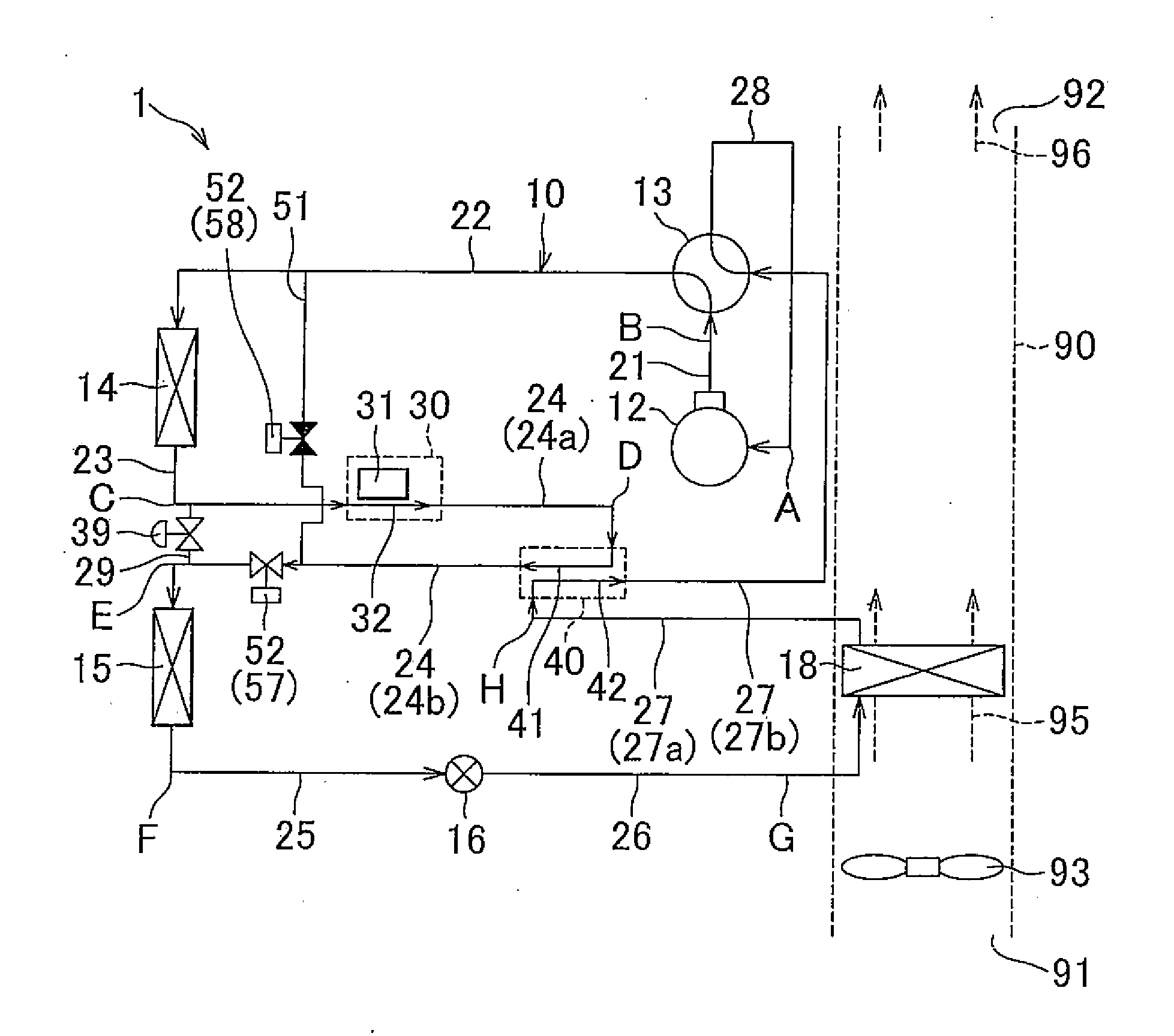
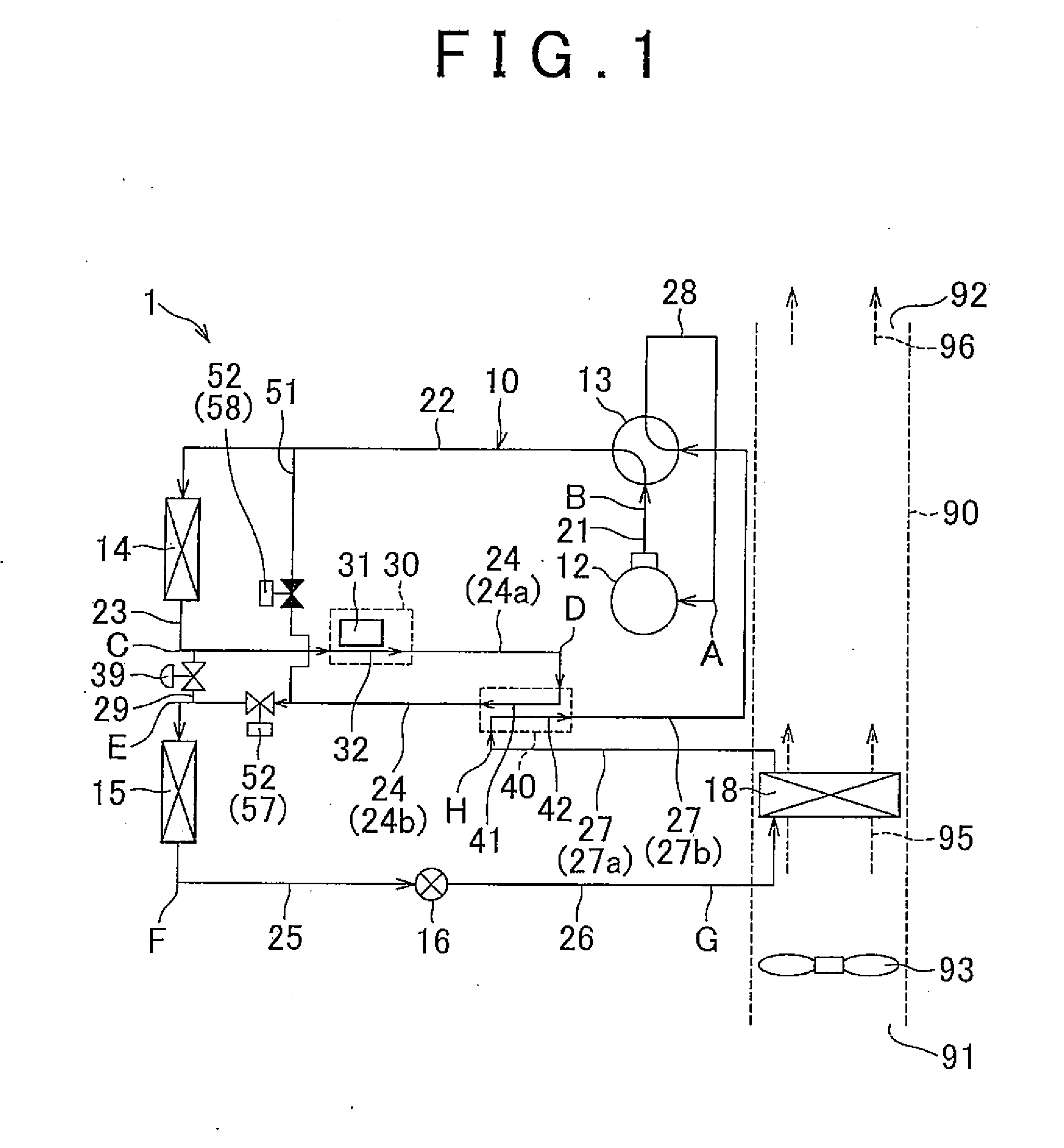
[0026]FIG. 1 is a schematic view that shows the configuration of a cooling system 1 according to a first embodiment. As shown in FIG. 1, the cooling system 1 includes a vapor compression refrigeration cycle 10. The vapor compression refrigeration cycle 10 is, for example, mounted on a vehicle in order to cool or heat the cabin of the vehicle. Cooling using the vapor compression refrigeration cycle 10 is performed, for example, when a switch for cooling is turned on or when an automatic control mode in which the temperature in the cabin of the vehicle is automatically adjusted to a set temperature is selected and the temperature in the cabin is higher than the set temperature. Heating using the vapor compression refrigeration cycle 10 is performed, for example, when a switch for heating is turned on or when the automatic control mode is selected and the temperature in the cabin is lower than the set temperature.

[0027]The vapor compression refrigeration cycle 10 includes a compressor ...

second embodiment

[0098]FIG. 8 is a schematic view that shows the configuration of a cooling system 1 according to a second embodiment. The cooling system 1 according to the second embodiment differs from the cooling system 1 according to the first embodiment in that the heat exchanger 14 and the heat exchanger 15 are manufactured as an integrated heat exchanger.

[0099]FIG. 9 is a schematic view that shows an example of the internal structure of the heat exchangers 14 and 15 according to the second embodiment. As shown in FIG. 9, the heat exchanger 14 and the heat exchanger 15 are integrally arranged. The integrally arranged heat exchanger 14 and heat exchanger 15 are, for example, provided next to an engine cooling radiator mounted on the vehicle, and carries out heat exchange between running wind of the vehicle or cooling air supplied by a cooling fan and refrigerant.

[0100]The heat exchanger 14 includes a plurality of tubes 146 through which refrigerant flows and a plurality of fins 148 that are use...


PUM


Abstract

A cooling system (1) includes: a compressor (12) that circulates refrigerant; a heat exchanger (14) and a heat exchanger (15) that carry out heat exchange between refrigerant and outside air; a decompressor (16) that decompresses refrigerant; a heat exchanger (18) that carries out heat exchange between refrigerant and air-conditioning air; a cooling portion (30) that is provided in a path of refrigerant flowing between the heat exchanger (14) and the heat exchanger (15) and that uses refrigerant to cool a heat generating source (31); a first line (24) through which refrigerant circulates between the cooling portion (30) and the heat exchanger (15); a second line (27) through which refrigerant circulates between the heat exchanger (18) and the compressor (12); and an internal heat exchanger (40) in which refrigerant that circulates through the first line (24) and refrigerant that circulates through the second line (27) exchange heat with each other.

Description

BACKGROUND OF THE INVENTION[0001]1. Field of the Invention[0002]The invention relates to a cooling system and, more particularly, to a cooling system that utilizes a vapor compression refrigeration cycle to cool a heat generating source.[0003]2. Description of Related Art[0004]In recent years, hybrid vehicles, fuel cell vehicles, electric vehicles, and the like, that run using driving force of a motor become a focus of attention as one of measures against environmental issues. In such vehicles, electrical devices, such as a motor, a generator, an inverter, a converter and a battery, exchange electric power to generate heat. Therefore, these electrical devices need to be cooled. Then, there has been suggested a technique that utilizes a vapor compression refrigeration cycle, which is used as a vehicle air conditioner, to cool a heat generating element.[0005]For example, Japanese Patent Application Publication No. 2006-290254 (JP 2006-290254 A) describes a cooling system for a hybrid ...

Claims


Application Information

Patent Timeline
IPC IPC(8): F25B1/00
CPCF25B1/005B60H1/00278B60H1/00907B60H2001/00307B60H2001/00935B60H2001/00949B60H2001/00957F25B13/00F25B40/00F25B2313/025F25B2313/02741F25B30/02
Inventor OHNO, YUICHIUCHIDA, KAZUHIDEJOJIMA, YUKIKAWAKAMI, YOSHIAKITAKAHASHI, EIZOSATO, KOUSUKE
Owner TOYOTA JIDOSHA KK
Why Eureka
Try Eureka