This helps you quickly interpret patents by identifying the three key elements:
Problems solved by technology
Method used
Benefits of technology
Benefits of technology
The present invention is a pressure point inspection device that aims to save time and improve inspection efficiency by automating the process of inspecting pressure points on liquid crystal display panels. The device utilizes adjustable gaps between the lateral and vertical adjustment boards, as well as multiple inspection heads that can be pressed against multiple pressure points on the panel, allowing for quicker and more comprehensive inspection. The device's simple structure makes it easy to adjust and avoids missing pressure points.
Problems solved by technology
In addition, the manual inspection may accidentally miss a pressure point, leading to inaccurate inspection and resulting in poor quality.
Method used
Image
Click on the blue label to locate the original text in one second.
Reading with bidirectional positioning of images and text.
Examples
first embodiment
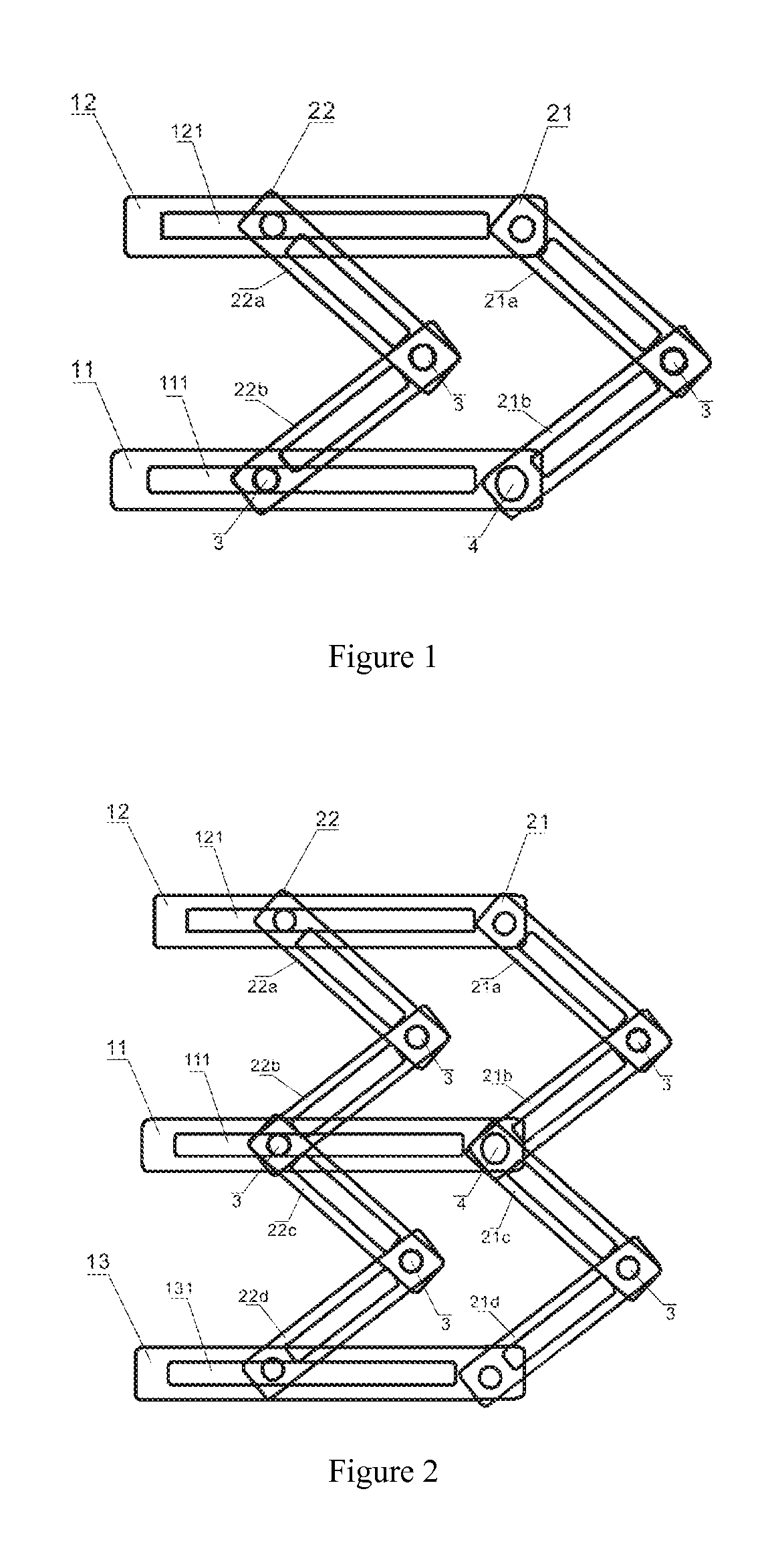
[0027]Referring to FIG. 1, FIG. 1 is a schematic view showing the structure of the pressure point inspection device according to the present invention.
[0028]In the instant embodiment, the pressure point inspection device comprises: a lateral adjustment board and a vertical adjustment board, disposed crossly on the lateral adjustment board, wherein the lateral adjustment board comprises two long stripe boards of the same shape, that is, a first lateral board 11 and a second lateral board 12, respectively. The first lateral board 11 and the second lateral board 12 are disposed in parallel.
[0029]The central part of the first lateral board 11 and the second lateral board 12 is disposed respectively with a sliding trench 111, 112 of the same length, for constraining the movement of vertical adjustment board.
[0030]The vertical adjustment board comprises two boards of the same shape and disposed in parallel; that is, a first vertical board 21 and a second vertical board 22. The following d...
second embodiment
[0046]FIG. 2 is a schematic view showing the structure of the pressure point inspection device according to the present invention.
[0047]The present embodiment differs from the first embodiment in that: the plurality of lateral adjustment boards further comprises a third lateral board 13 of the same shape and size as the first lateral board 11. The third lateral board 13 is located below the first lateral board 11, and is also disposed with sliding trench 131 parallel to the sliding trenches 111, 121.
[0048]The first vertical board 21 comprises four support rods 21a, 21b, 21c, 21d of the same shape and size, and engaged sequentially by joints. The second vertical board 22 comprises four support rods 22a, 22b, 22c, 22d of the same shape and size, and engaged sequentially by joints. Each of the six connected positions of the two vertical boards 21, 22 and three lateral boards 11, 12, 13 is disposed with a rubber head for pressing, and all the rubber heads are in the same plane. A fasten...
third embodiment
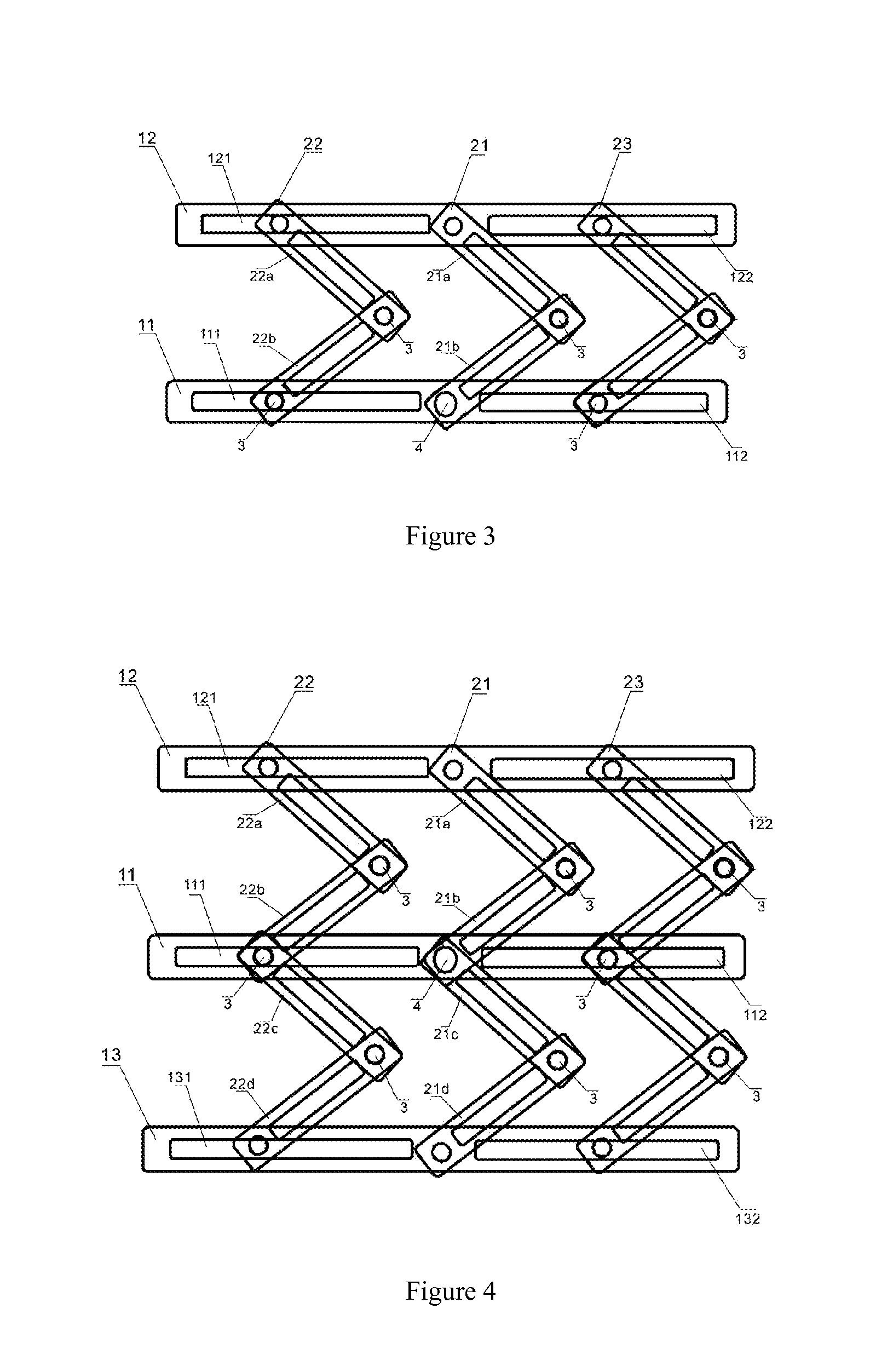
[0051]FIG. 3 is a schematic view showing the structure of the pressure point inspection device according to the present invention.
[0052]The present embodiment differs from the first embodiment in that: the plurality of vertical adjustment boards further comprises a foldable third vertical board 23 of the same shape and structure as the first vertical board 21.
[0053]The first lateral board 11 is disposed with two sliding trenches 111, 112 on two sides, and the second lateral board 12 is disposed with two sliding trenches 121, 122 on two sides. The two ends of the third vertical board 23 are constrained respectively inside the sliding trenches 112, 122. At the same time, each of the six connected positions of the three vertical boards 21, 22, 23 and two lateral boards 11, 12 is disposed with a rubber head for pressing, and all the rubber heads are in the same plane.
PUM
Abstract
The present invention discloses a pressure point inspection device, able to press on a plurality of pressure points on liquid crystal display panel for inspecting display condition, the pressure point inspection device includes: lateral adjustment board, lateral adjustment board including a first lateral board and a second lateral board; vertical adjustment board, disposed crossly on lateral adjustment board, vertical adjustment board including first vertical board and second vertical board, able to fold separately; wherein lateral adjustment board and / or vertical adjustment board disposed with a plurality of inspection heads, vertical disposition gap between first lateral board and second lateral board adjustable and lateral disposition gap between first vertical board and second vertical board adjustable. As such, the pressure point inspection device can save time of pressing pressure points on TFT-LCD and improve inspection efficiency and avoid missing pressure point.
Description
BACKGROUND OF THE INVENTION[0001]The present application claims priority of “PRESSURE POINT INSPECTION DEVICE”, application number 201210406628.2 submitted to State Intellectual Property Office, People Republic of China dated Oct. 23, 2012.[0002]1. Field of the Invention[0003]The present invention relates to the field of liquid crystal panel manufacturing techniques, and in particular to a pressure point inspection device.[0004]2. The Related Arts[0005]Thin film transistorliquid crystal display (TFT-LCD) has become an important display platform of current IT and video conferencing products. The operating theory of TFT-LCD is through appropriate voltage loading in liquid crystal layer to make the liquid crystal molecules diffract under the influence of the voltage, and to obtain different penetration ratio by different voltage control to realize displaying.[0006]In the manufacturing process of TFT-LCD, the product requires inspecting the screen. As shown in FIG. 5, FIG. 5 is a schem...
Claims
Application Information
Patent Timeline
Application Date:The date an application was filed.
Publication Date:The date a patent or application was officially published.
First Publication Date:The earliest publication date of a patent with the same application number.
Issue Date:Publication date of the patent grant document.
PCT Entry Date:The Entry date of PCT National Phase.
Estimated Expiry Date:The statutory expiry date of a patent right according to the Patent Law, and it is the longest term of protection that the patent right can achieve without the termination of the patent right due to other reasons(Term extension factor has been taken into account ).
Invalid Date:Actual expiry date is based on effective date or publication date of legal transaction data of invalid patent.

