
Tubular heat exchanger

a technology of heat exchanger and tubular tube, which is applied in the direction of superimposed coating process, corrosion prevention, stationary tubular conduit assembly, etc., can solve the problems of reduced space in factories, difficult positioning of tubular tube in closed spaces, and production of treated products whose thermal characteristics may not be suitable for us

Inactive Publication Date: 2014-04-24
AURUM FOODS
View PDF7 Cites 14 Cited by
  • Summary
  • Abstract
  • Description
  • Claims
  • Application Information

AI Technical Summary

Benefits of technology

The invention is a heat exchanger with a unique design that improves energy efficiency and prevents dead areas. The design has holes in each plate that direct the product to be treated through a specific path, eliminating areas of low heat transfer. Additionally, the design reduces the size of the heat exchanger because large surfaces are not needed to achieve high heat transfer. The scraped surface of the exchanger allows for long continuous working times.

Problems solved by technology

Depending on the amount of product to be treated, the sizes of the sleeves vary greatly, even being able to take up very large volumes which make positioning them in closed spaces difficult, and it involves the reduction of space in factories.
However, even though this solution successfully improves the heat transfer with respect to the exchanger that has no compartments, the product does not flow through the entire volume of said compartments inside the chamber, there being small dead areas that, though being much smaller than in the exchanger that has no compartments, continue to cause the production of a treated product the thermal characteristics of which may not be the initially desired characteristics.

Method used


Image

  • Tubular heat exchanger
  • Tubular heat exchanger
  • Tubular heat exchanger

Examples


Embodiment Construction

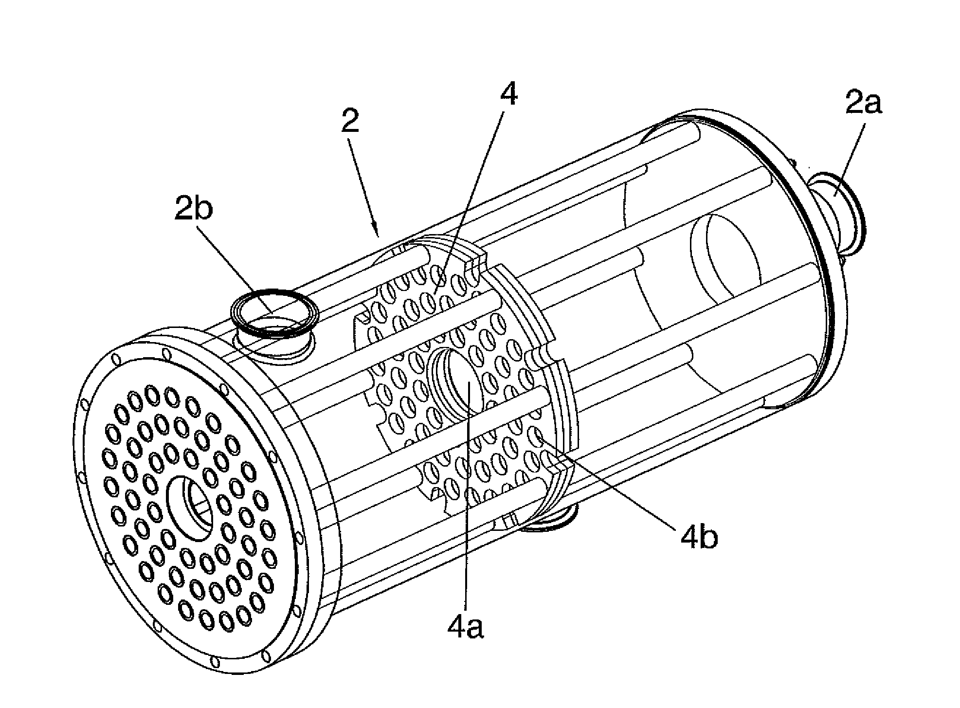
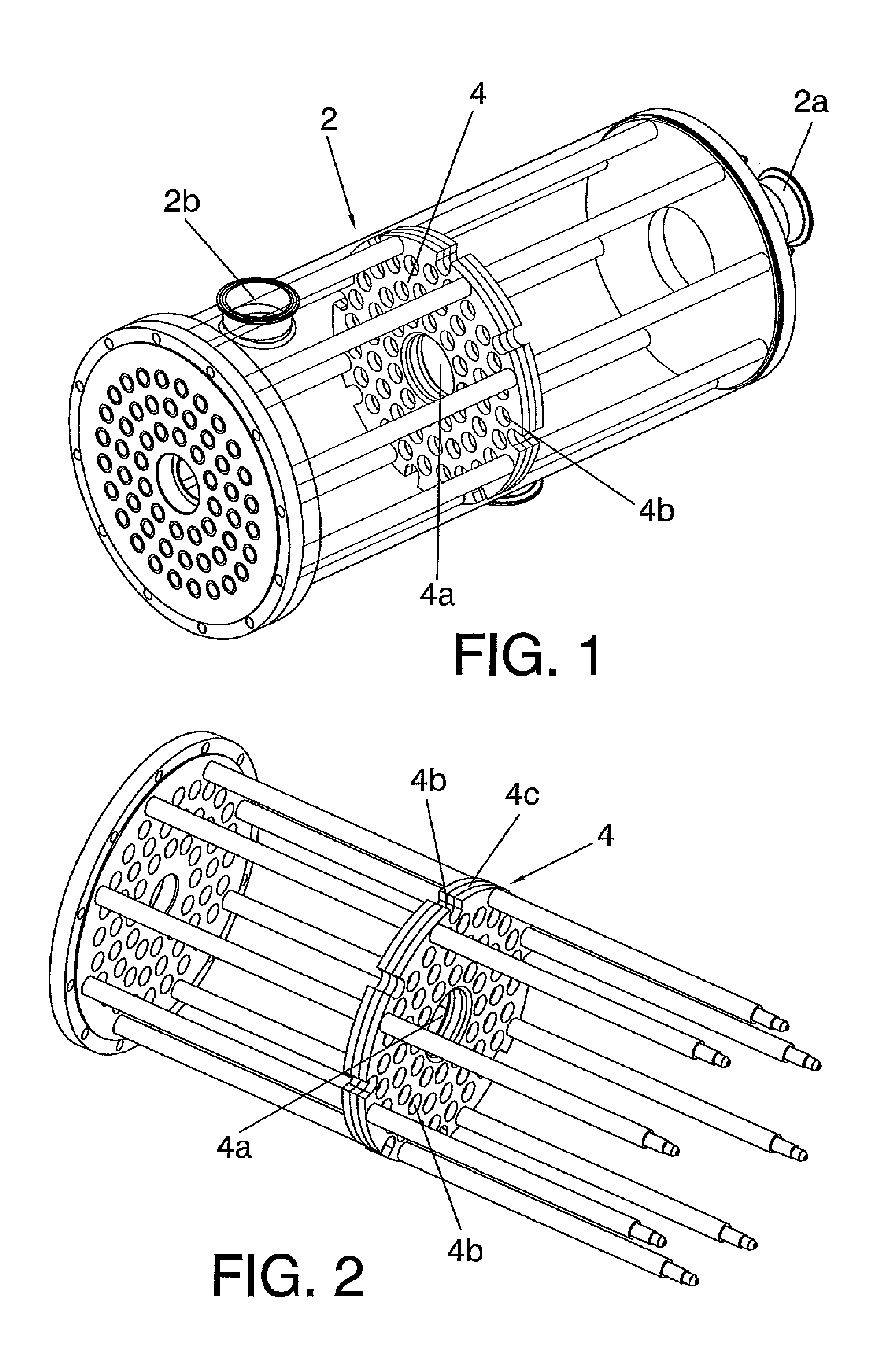
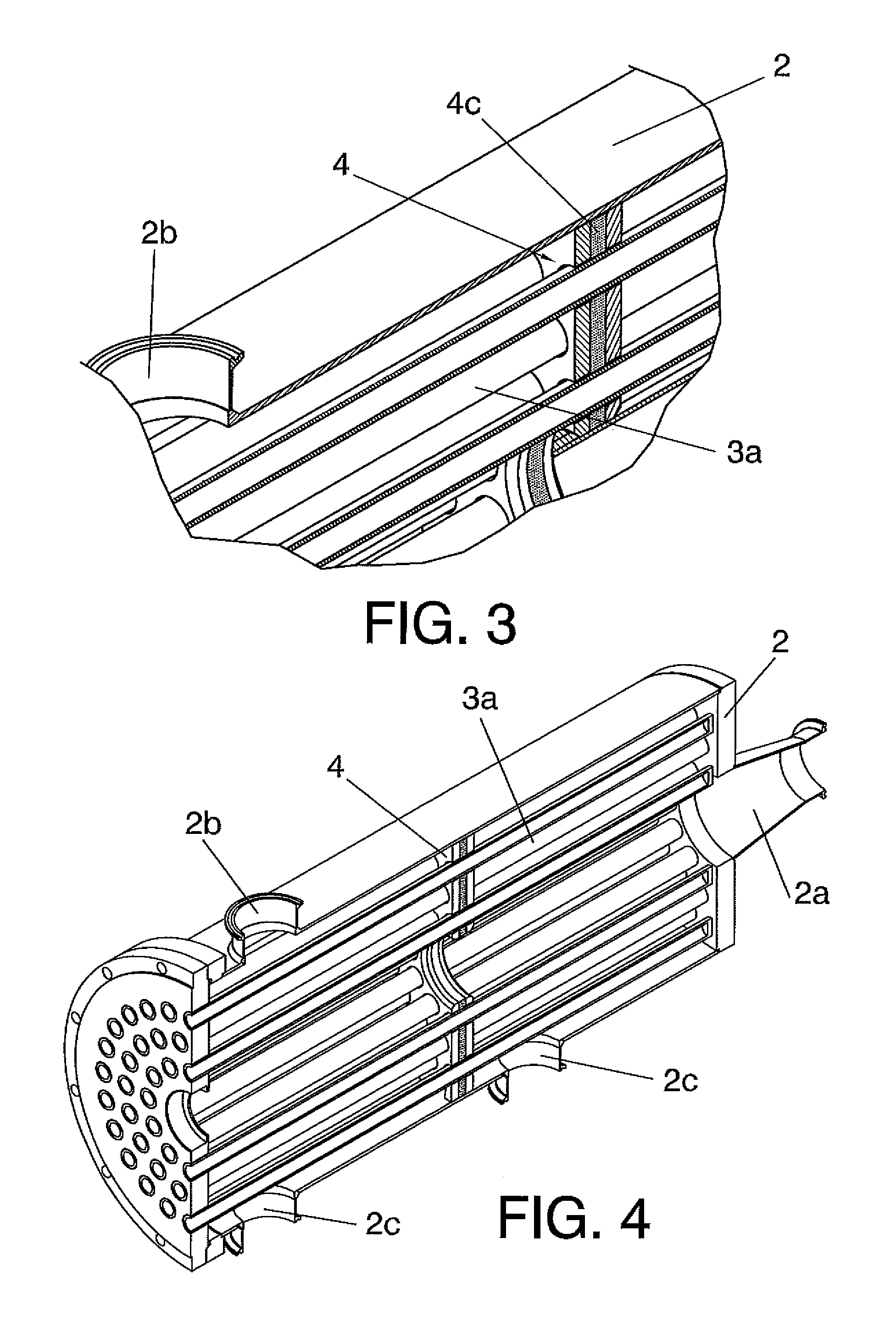
[0009]The present invention relates to a tubular heat exchanger comprising the following technical features:[0010]a tubular sleeve comprising an inlet for the entrance of a product to be thermally treated, and an outlet for the exit of said thermally treated product;[0011]a first plurality of tubes carrying a heat transfer fluid which are located inside the tubular sleeve; where said first plurality of tubes can be of one and the same tube wound inside the exchanger, or can be part of independent tubes with a common inlet for the entrance of the heat transfer fluid, and an also common outlet for the exit of said heat transfer fluid;[0012]at least one diaphragm located inside the tubular sleeve which divides the interior of the sleeve into at least two chambers, where said diaphragm comprises a central hole configured for allowing the passage of the product from the inlet to the outlet of the sleeve; and where said diaphragm comprises a plurality of holes configured for allowing the ...


PUM

PropertyMeasurementUnit
diameteraaaaaaaaaa
outer diameteraaaaaaaaaa
perimeteraaaaaaaaaa

Abstract

The present specification describes a tubular heat exchanger (1) comprising a tubular sleeve (2); a first plurality of tubes (3a) carrying a heat transfer fluid which are located inside the tubular sleeve (2); at least one diaphragm (4) located inside the tubular sleeve (2) which divides the interior of the sleeve (2) into at least two chambers, where said diaphragm comprises a central hole (4a) configured for allowing the passage of the product, and where said diaphragm (4) comprises a plurality of holes (4b) configured for allowing the passage of the first plurality of tubes (3a); and a piston (5) comprising a tubular shaft (5a) and at least two plates (6) perpendicular to the tubular shaft (5a); where said tubular shaft (5a) is configured for performing a longitudinal reciprocating movement through the central hole (4a) of said at least one diaphragm (4); improving the heat transfer of the exchanger object of the invention.

Description

TECHNICAL FIELD OF THE INVENTION[0001]The present invention relates to a tubular heat exchanger configured for transferring heat from a heat transfer fluid to a specific product, or vice versa; where said heat exchange includes heating and cooling processes as well as drying processes; and where the heat exchanger object of the invention is encompassed within the field of food preservation and preparation.[0002]The purpose of this heat exchanger is to perform tasks of heating, cooling or drying products that can be both foods, in a preferred embodiment, and any other type of products that must be heated or cooled, such as sludge in waste water treatment plants, for example. Said exchanger furthermore allows improving the energy efficiency of heat transfer with respect to the exchangers known until now, having a small and compact size, in addition to reducing the heat treatment time depending on the type of product to be treated.BACKGROUND OF THE INVENTION[0003]By way of introduction...

Claims


Application Information

Patent Timeline
Patent Type & Authority Applications(United States)
IPC IPC(8): F28F1/00
CPCF28F1/00C02F11/12C02F11/18C23C28/321C23C28/322C23C28/34C23C28/345C23C28/3455C02F11/13F28D7/12F28D7/1646F28D7/1676F28D2021/0042F28F5/00F28F9/02F28F9/0229F28F13/06F28F19/008F28F27/02F28G1/08F24S70/25F24S70/30Y02E10/40
Inventor PAGAN DURAN, JES S
Owner AURUM FOODS
Learn More