Liquid crystal display device

a liquid crystal display and display device technology, applied in non-linear optics, instruments, optics, etc., can solve the problems of not being able to sense the appropriate position, not considering the need to improve the viewing angle property, and not being able to visually recognize the obj

Active Publication Date: 2014-04-24
NEC LCD TECH CORP
View PDF7 Cites 6 Cited by
  • Summary
  • Abstract
  • Description
  • Claims
  • Application Information

AI Technical Summary

Problems solved by technology

However, with the liquid crystal display device disclosed in Patent Document 1 described above, there is such an issue that moiré is likely to be visually recognized when two-dimensional videos are displayed.
Further, there is no consideration being taken to satisfy the demand for improving the viewing angle property.
However, when the liquid crystal display device is displaying a two-dimensional video, the observer cannot sense the appropriate positions.
Thus, there may be cases where the eyes are located at the region visually recognized as black depending on the position of the face, which may deteriorate the display quality greatly.
There is a limit for set for reducing the width of the data line 62 in terms of the manufacture process, so that it is difficult to reduce the width e in the case of FIG. 30.
This causes an issue of deteriorating the numerical aperture.
Thus, when the electric field between the common electrode and the pixel electrodes is influenced by the electric field from the gate line or the data line, faults such as crosstalk and the like occur.
However, when the pixel layout (FIG. 30, FIG. 31) which reduces the moiré disclosed in Patent Document 2 and the pixel structure (FIG. 32, FIG. 33) of the IPS mode disclosed in Patent Document 5 are applied to the liquid crystal display device (FIG. 27, FIG. 28, FIG. 29) which displays three-dimensional videos disclosed in Patent Document 1, there is generated such a new issue that the numerical aperture is deteriorated greatly.
This may sometimes be called 3D crosstalk, and it becomes difficult for the observer to visually recognize an image as a three-dimensional video when the mixing ratio of the light becomes high.
That is, θ cannot be set small for securing the numerical aperture, so that the numerical aperture is deteriorated greatly.
Therefore, while the deterioration in the numerical aperture can be reduced, the moiré cannot be suppressed.

Method used


Image

  • Liquid crystal display device
  • Liquid crystal display device
  • Liquid crystal display device

Examples


first exemplary embodiment

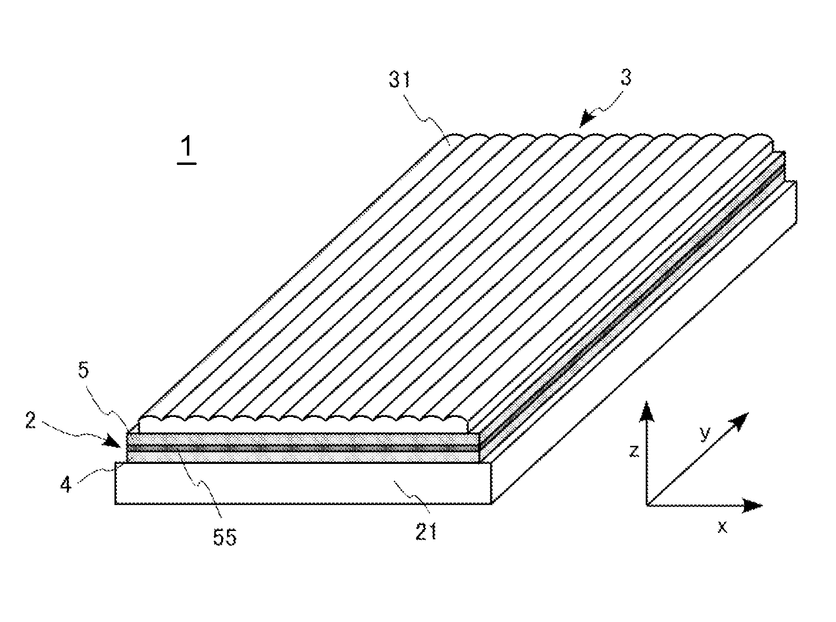
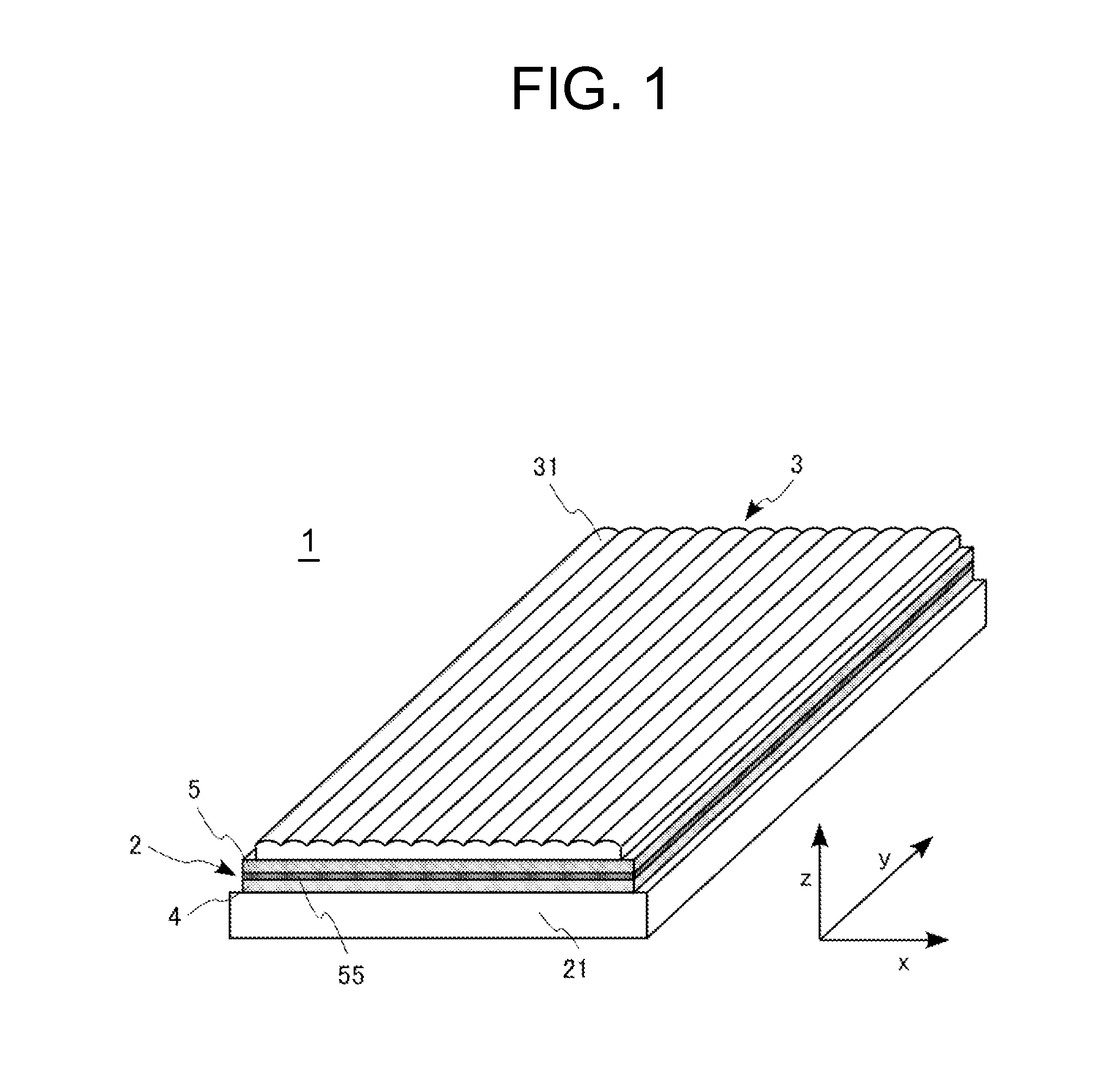
[0063]The liquid crystal display device according to the first exemplary embodiment is capable of displaying an image for the left eye and an image for the right eye, and it is capable of allowing an observer to visually recognize a three-dimensional video by displaying images different from each other to the left and right eyes of the observer.

[0064]As shown in FIG. 1, the liquid crystal display device 1 of the first exemplary embodiment is formed by disposing, on a liquid crystal panel 2, a lens array sheet 3 in which cylindrical lenses 31 are formed in an array form. Further, a backlight 21 is disposed on a surface that is in a reverse side of the lens surface of the liquid crystal panel 2.

[0065]Each of the cylindrical lenses 31 constituting the lens array sheet 3 is extended in the Y-axis direction and disposed in an array form along the X-axis direction. The cylindrical lens 31 does not exhibit the lens effect in the Y-axis direction (extending direction of the lens) but exhibi...

second exemplary embodiment

[0095]A liquid crystal display device according to a second exemplary embodiment has almost the same structures as those of the liquid crystal display device according to the first exemplary embodiment, and the layout of the aperture section of the sub-pixel is different. Therefore, the pixel layout and the circuit structure of the second exemplary embodiment are the same as those of the first exemplary embodiment, and the CF substrate having the layout of FIG. 5 is also used herein. FIG. 12 shows the layout of the aperture section 61a of the sub-pixel 61 when the TFT substrate and the CF substrate are superimposed in the liquid crystal display device according to the second exemplary embodiment.

[0096]In the liquid crystal display device of the second exemplary embodiment, there is the aperture section 61a that is defined with a dotted line E-E′ as well as a dotted line F-F′ defining the height of the aperture section 61a of the sub-pixel 61 in the Y-axis direction, and a dotted lin...

third exemplary embodiment

[0104]A liquid crystal display device according to a third exemplary embodiment has almost the same structures as those of the liquid crystal display device according to the first exemplary embodiment, and the layout of the aperture section of the sub-pixel is different. Therefore, the pixel layout and the circuit structure of the third exemplary embodiment are the same as those of the first exemplary embodiment, and the CF substrate having the layout of FIG. 5 is also used herein. FIG. 14 shows the layout of the aperture section 61a of the sub-pixel 61 when the TFT substrate and the CF substrate are superimposed in the liquid crystal display device according to the third exemplary embodiment.

[0105]In the liquid crystal display device of the third exemplary embodiment, there is the aperture section 61a that is defined with a dotted line E-E′ as well as a dotted line F-F′ defining the height of the aperture section 61a of the sub-pixel 61 in the Y-axis direction and a dotted line B-B...


PUM

PropertyMeasurementUnit
electric fieldaaaaaaaaaa
angleaaaaaaaaaa
voltageaaaaaaaaaa

Abstract

A liquid crystal display device is constituted such that sub-pixels are disposed in an array form in a first direction and a second direction orthogonal to each other, a plurality of gate lines are disposed in the second direction, an optical element for distributing the light to the second direction is disposed on the liquid crystal display device, liquid crystal molecules of the liquid crystal display device are controlled by an electric field almost in parallel to the surface of the liquid crystal display device, and a data line is disposed to obliquely divide the sub-pixels at a position different from the boundary between the sub-pixels neighboring in the second direction, where the data line can have a small angle with respect to the second direction, and the numerical aperture is not deteriorated greatly even when the lengths of apertures of the sub-pixels in the first direction are constant.

Description

CROSS-REFERENCE TO RELATED APPLICATION[0001]This application is based upon and claims the benefit of priority from Japanese patent application No. 2012-231866, filed on Oct. 19, 2012, the disclosure of which is incorporated herein in its entirety by reference.BACKGROUND OF THE INVENTION[0002]1. Field of the Invention[0003]The present invention relates to a liquid crystal display device and, more specifically, to a liquid crystal display device which displays three-dimensional videos.[0004]2. Description of the Related Art[0005]Recently, there has been a rapidly increasing demand for a display capable of displaying three-dimensional videos, i.e., so-called 3D videos. A large number of researches and studies on the techniques for displaying the three-dimensional videos have been done from the past, and studies and developments thereof are actively conducted at present as well. Among those, one of the techniques considered as most potential currently is the technique using binocular pa...

Claims


Application Information

Patent Timeline
Patent Type & Authority Applications(United States)
IPC IPC(8): G02F1/1343
CPCG02F1/134309G02F1/133526G02F1/134363G02F1/136286
Inventor SEKINE, HIROYUKI
Owner NEC LCD TECH CORP
Why Eureka
Try Eureka