Honing Tool

a honing tool and tool body technology, applied in the field of honing tools, can solve the problems of increasing the cost of honing stones and the small space available in the tool body, and achieve the effects of preventing tilting or canting, enhancing the torsion stiffness of the tool body in operation, and improving the mounting and exchange of honing stones

Inactive Publication Date: 2014-04-24
GEHRING TECH
View PDF11 Cites 9 Cited by
  • Summary
  • Abstract
  • Description
  • Claims
  • Application Information

AI Technical Summary

Benefits of technology

[0011]With the spring element according to the invention which is integrated completely into the tool body of the honing tool, it is possible to exert a spring force in radial direction onto the honing stone which forces the honing stone in radial direction inwardly into the tool body. In this way, it is ensured that, firstly, the honing stone always remains in contact with a wedge surface of the feed rod and that, secondly, upon retraction of the feed rod the honing stone is returned into its rest position by the spring force of the spring element, i.e., is forced in radial direction inwardly into the tool body. The spring element according to the invention is very small with respect to its dimensions, in particular, when it is made of spring wire (diameter e.g. 0.3 mm-1.0 mm). As a result of this, the tool body of the honing tool must be weakened only minimally in order to accommodate and radially secure the spring element. In this context, sufficiently large spring travel and, simultaneously, satisfactory spring or restoring forces can be provided by appropriately selecting the length of the spring element and the pretension of the spring element.
[0028]The securing elements or the spring elements are preferably manufactured of wire, in particular spring wire. Therefore, they are inexpensive with respect to manufacture, are very load-resistant, and require only little space for installation.

Problems solved by technology

In honing tools for machining bores with small diameters (i.e., smaller than 15 mm), there is of course little space available in the tool body.
This embodiment increases also the costs of the honing stone.

Method used


Image

  • Honing Tool
  • Honing Tool
  • Honing Tool

Examples


Embodiment Construction

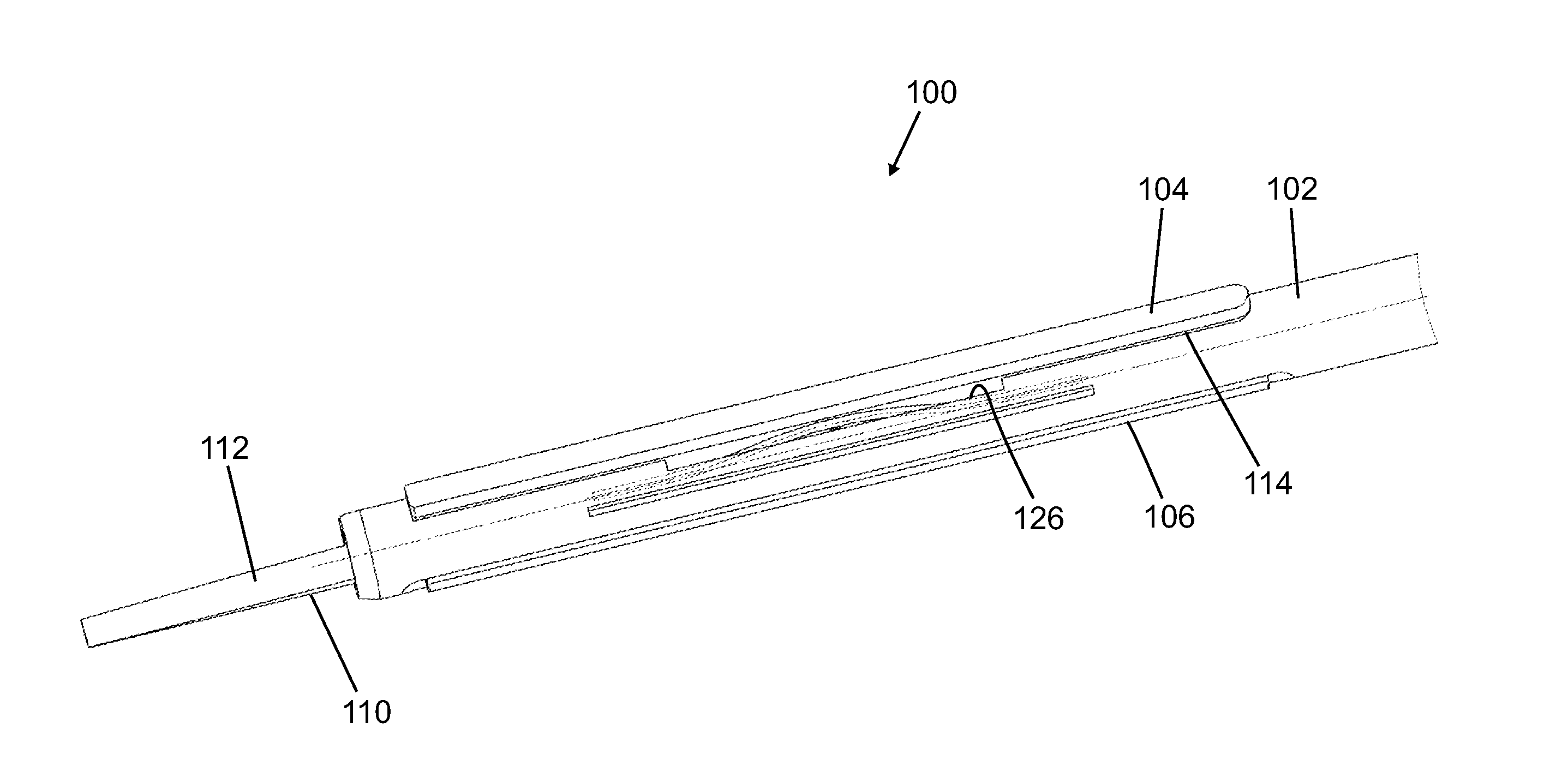
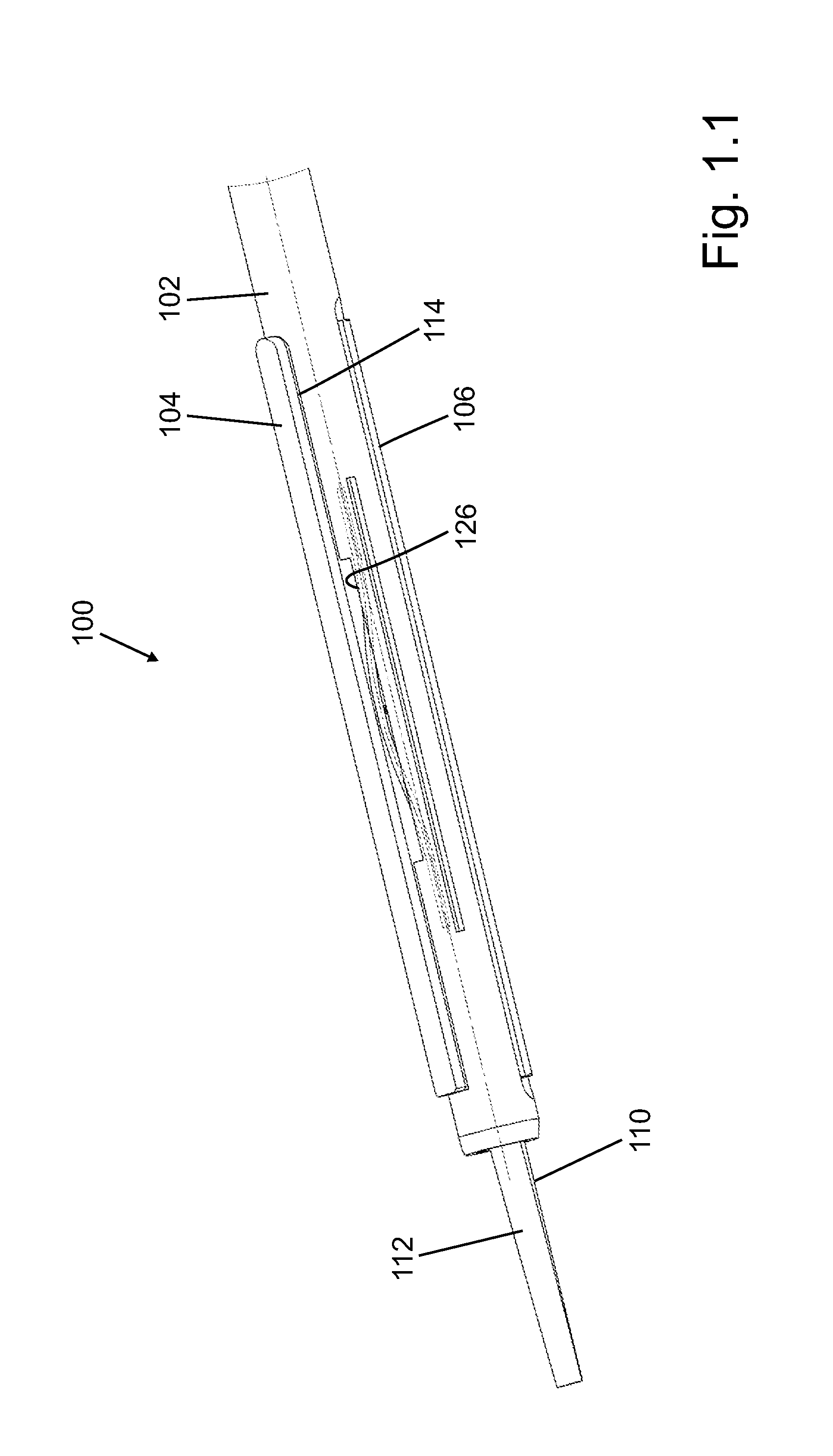
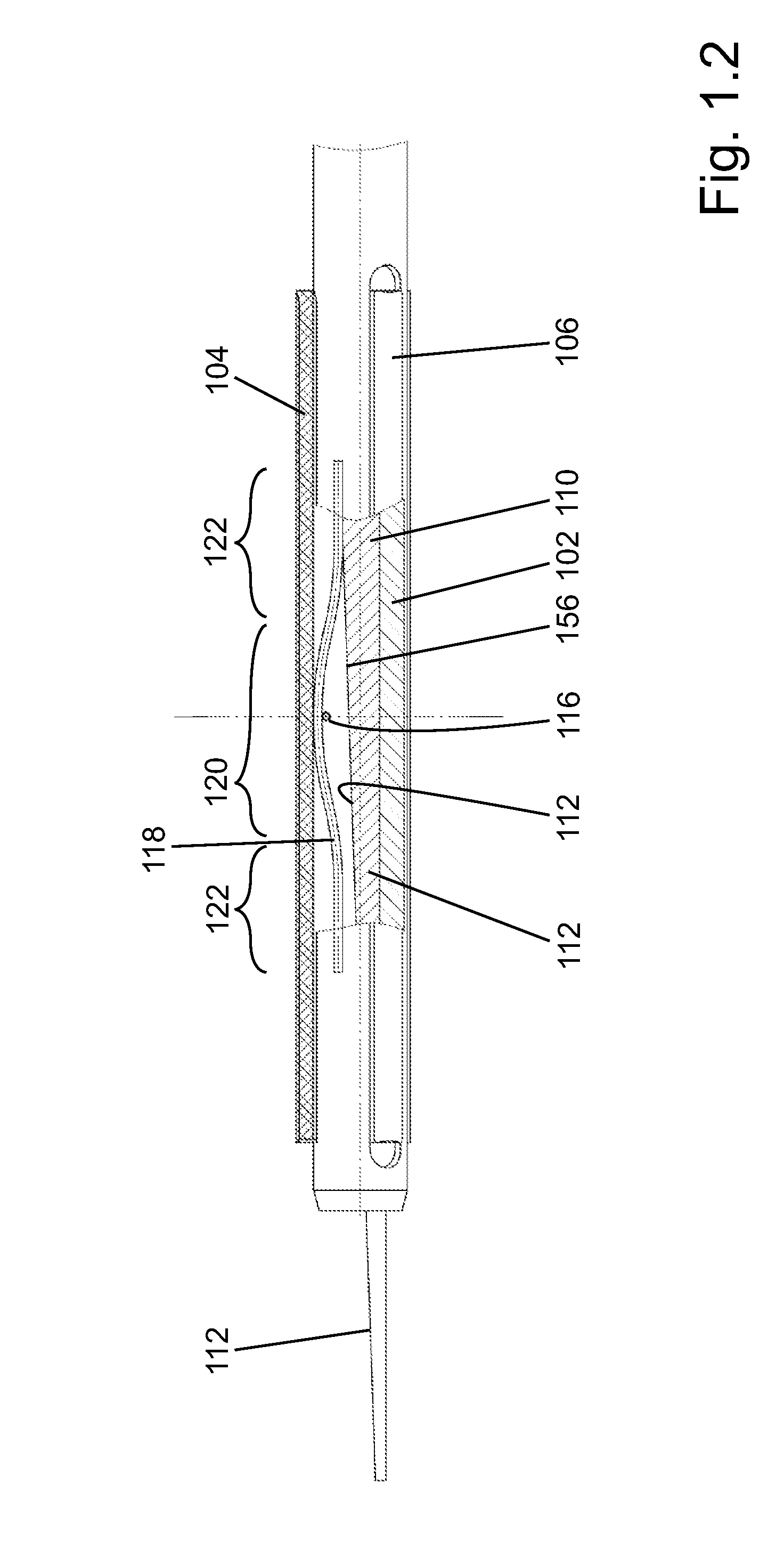
[0045]The honing tool 100 illustrated in FIG. 1 is used in particular for machining small bores, i.e., bores with a diameter of less than 15 mm. It is embodied as a single honing stone tool with tool body 102 and a radially adjustable honing stone 104. In order for the honing tool 100 to be centered within the bore to be machined (not illustrated), one or two guide bars 106 are attached to the tool body 102.

[0046]In order to effect radial feeding of the honing stone 104, in the interior of the tool body 102 a feed bore 108 is formed (see FIG. 1.3) in which a feed rod 110 is axially slidably guided. The feed rod 110 has a wedge surface 112 which is interacting with an appropriately slanted bottom side 156 of the honing stone 104 in such a way that, upon axial movement of the feed rod 110 relative to the tool body 102, the honing stone 104 is advanced radially in outward direction. This type of feeding action is known in the prior art and therefore requires no further explanation.

[004...


PUM


Abstract

A honing tool for machining cylindrical bores has a tool body provided with a guide bore and a feed rod disposed in the guide bore. The tool body has a honing stone receptacle extending from the guide bore in a radial direction of the tool body outwardly through the tool body. A honing stone is arranged in the honing stone receptacle. A pin is disposed in the honing stone and projects laterally from the honing stone. An elongate spring is disposed in the tool body parallel to the honing stone, wherein the elongate spring element has a first end section, a central section, and a second end section opposite the first end section. The central section is guided across the pin and the first end section is secured in the radial direction in the tool body.

Description

BACKGROUND OF THE INVENTION[0001]The invention relates to a honing tool for machining cylindrical bores, wherein the honing tool has a tool body and in the tool body a guide bore for a feed rod is formed. The honing tool further comprises at least one honing stone receptacle that is extending from the guide bore radially in outward direction through the tool body and is designed for receiving at least one honing stone.[0002]In honing tools known in the art, the dimensions of the usually rectangular honing stone receptacle and of the corresponding honing stones are matched to each other such that the honing stone is received and guided between the boundary surfaces of the honing stone receptacle so as to be radially movable and arranged without play in the circumferential direction of the tool body. Generally, by precise machining of the boundary surfaces of the honing stone receptacle and of the corresponding lateral surfaces of the honing stone, it is attempted to realize a sliding...

Claims


Application Information

Patent Timeline
Patent Type & Authority Applications(United States)
IPC IPC(8): B24B33/08B24B33/02
CPCB24B33/02B24B33/08B24B33/082
Inventor BAUMGARTNER, ERWINNECKER, JORGFLECKENSTEIN, KLAUSSENKE, ANDREASHUMMEL, FRANKWEBER, ALEXANDER CHRISTIAN
Owner GEHRING TECH
Why Eureka
Try Eureka