
Wireless engine monitoring system with multiple hop aircraft communications capability and on-board processing of engine data

a technology of engine data and communication capability, applied in the field of real-time monitoring of aircraft engines, can solve the problems of high cost of retrieving what may or may not have been the full flight engine data from the aircraft, non-gdl prior art monitoring systems, and high bandwidth requirements for overly large engine data files. non-gdl systems cannot deliver,

Active Publication Date: 2014-04-24
HARRIS CORP
View PDF12 Cites 33 Cited by
  • Summary
  • Abstract
  • Description
  • Claims
  • Application Information

AI Technical Summary

Benefits of technology

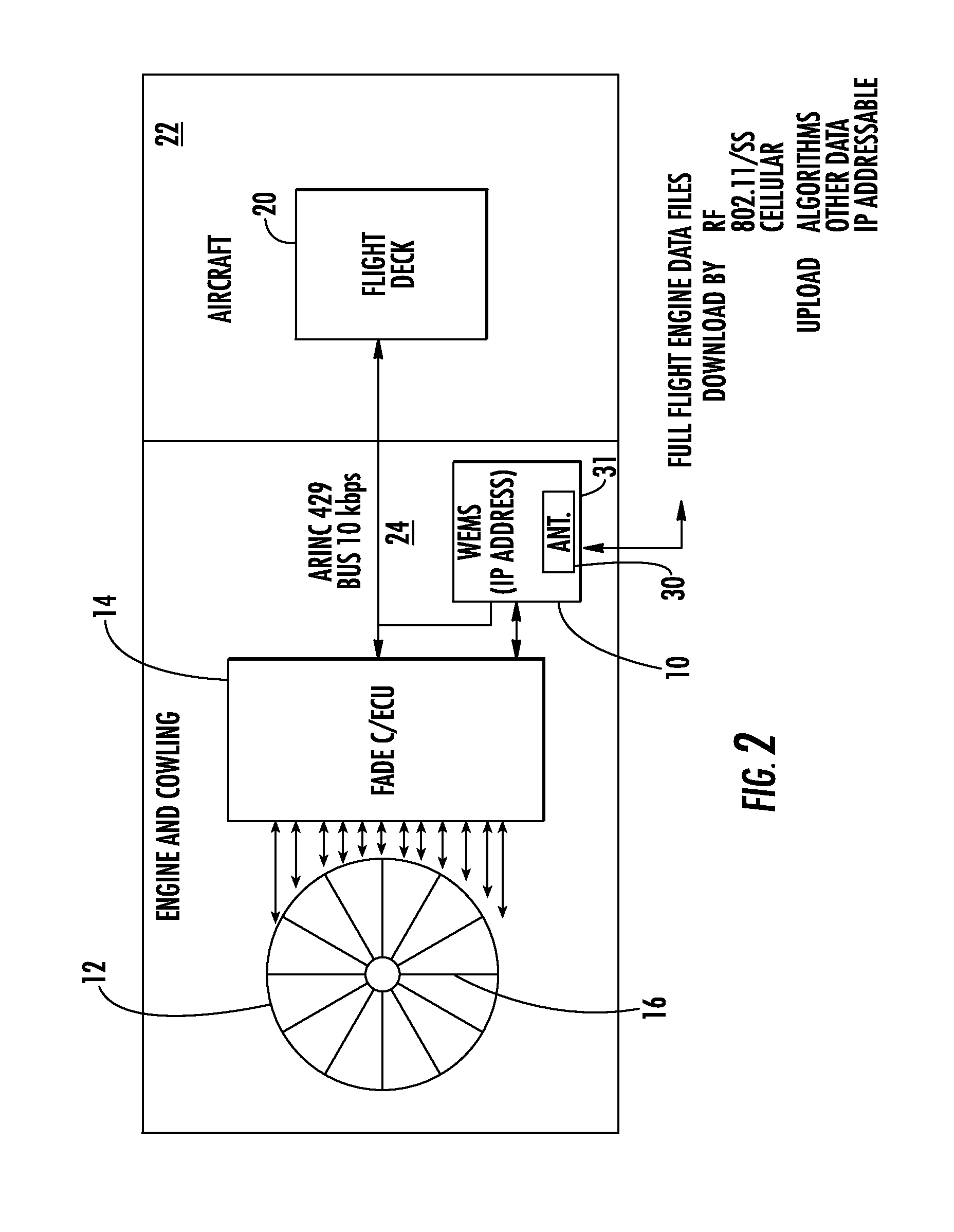
A monitoring system for an aircraft engine has been developed. The system includes a housing that is mounted on the engine and has a first wireless transmitter to collect and store engine data from multiple sensors during operation. The data is transmitted to a wireless receiver also on the engine, which then retransmits it to a second wireless transmitter. The second wireless transmitter can use either an air-to-ground or satellite communications link to send the data. The system also includes a wireless LAN and a processor to analyze the data and make decisions about the engine's operating parameters, such as whether to shut it down during flight. The technical effect of this system is continuous monitoring of engine performance in real-time, allowing for timely maintenance and repair, and improving overall engine efficiency and reliability.

Problems solved by technology

Also, these non-GDL prior art monitoring systems as described not only had data collection of limited value, but also had a high cost for retrieving what may or may not have been the full flight engine data from the aircraft because of limited communication options, for example, limited frequencies and narrow bandwidth / spectrum available from the FCC at the aeronautical frequency spectrum.
The overly large engine data files required high bandwidth, e.g., about 10 kbps up to about 36 MB / FLT HR (without compression), which those non-GDL systems could not deliver.

Method used


Image

  • Wireless engine monitoring system with multiple hop aircraft communications capability and on-board processing of engine data
  • Wireless engine monitoring system with multiple hop aircraft communications capability and on-board processing of engine data
  • Wireless engine monitoring system with multiple hop aircraft communications capability and on-board processing of engine data

Examples


Embodiment Construction

[0029]The present invention will now be described more fully hereinafter with reference to the accompanying drawings, in which preferred embodiments of the invention are shown. This invention may, however, be embodied in many different forms and should not be construed as limited to the embodiments set forth herein. Rather, these embodiments are provided so that this disclosure will be thorough and complete, and will fully convey the scope of the invention to those skilled in the art. Like numbers refer to like elements throughout, and prime notation is used to indicate similar elements in alternative embodiments.

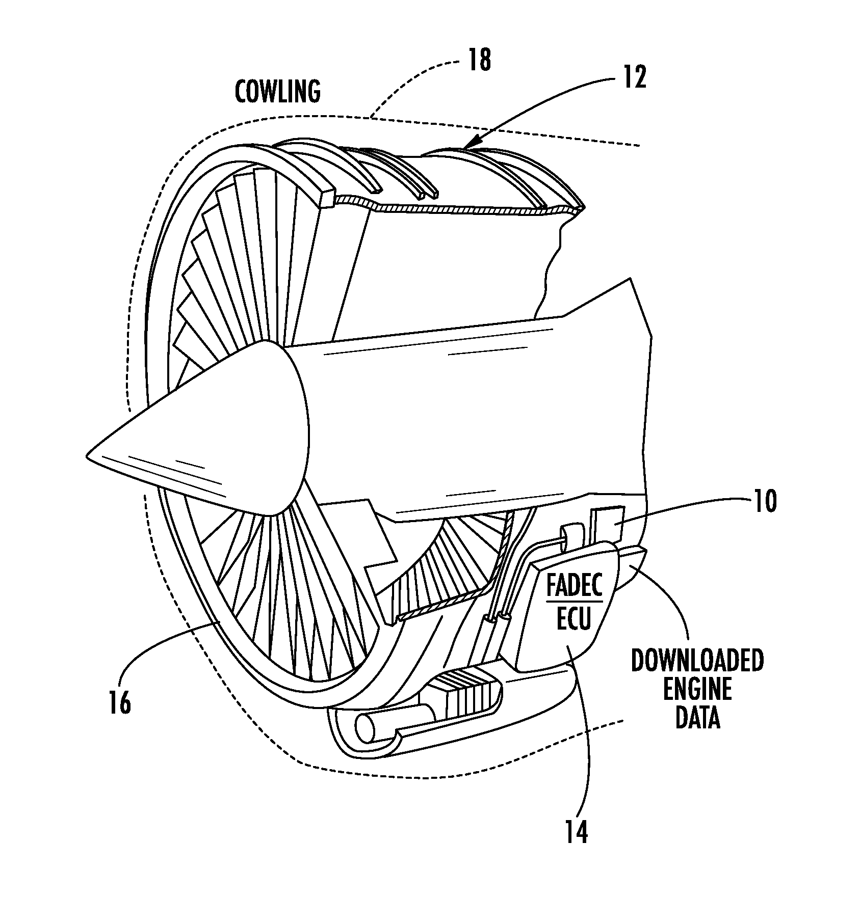
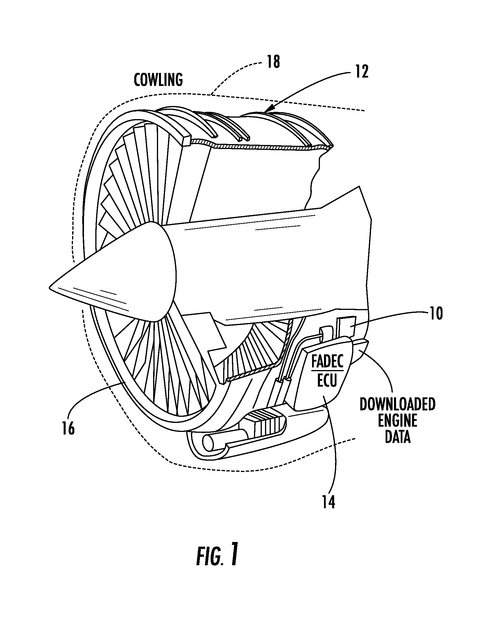
[0030]The wireless engine monitoring system (WEMS) as disclosed in the incorporated by reference '699, '756, '739 and '512 patents collects full flight engine data and is configured in one example to interoperate with basic components of the ground data link (GDL) unit as disclosed in the incorporated by reference '165, '179 and '734 patents. The WEMS module is mounted dire...


PUM


Abstract

An engine monitoring module includes a housing configured to be mounted at the aircraft engine and a first wireless transmitter carried by the housing. A memory is carried by the housing and a processor is carried by the housing and coupled to the memory and the first wireless transmitter and configured to collect and store in the memory engine data relating to at least one engine parameter sensed during operation of the aircraft engine by a plurality of engine sensors that transmit the engine data via the first wireless transmitter. A wireless receiver is located within the aircraft and configured to receive the engine data transmitted from the first wireless transmitter. A second wireless transmitter is located within the aircraft and operatively connected to the wireless receiver and configured to receive and transmit the engine data.

Description

FIELD OF THE INVENTION[0001]This invention relates to real-time monitoring of aircraft engines, and more particularly, this invention relates to systems and related methods for determining an aircraft engine's current performance by collecting real-time aircraft engine data and processing the engine data for engine maintenance or other analysis.BACKGROUND OF THE INVENTION[0002]Harris Corporation of Melbourne, Fla. has designed a system and method of recording performance of an aircraft engine using a ground data link unit that interfaces with numerous components of the aircraft, including the Digital Flight Data Acquisition Unit (DFDAU), the aircraft Digital Flight Data Recorder (DFDR), and the data multiplexing system commonly referred to as the Full Authority Digital Engine Control (FADEC) for larger jet turbine engines or the Engine Control Unit (ECU) as sometimes referred to with smaller jet turbine engines used on smaller aircraft, including turboprops or other engines generati...

Claims


Application Information

Patent Timeline
Patent Type & Authority Applications(United States)
IPC IPC(8): G01M15/14
CPCG01M15/14G05B23/0213B64D2045/0085
Inventor ZIARNO, JAMES J.
Owner HARRIS CORP
Learn More