Method For Monitoring And Measuring An Insulation Resistance With Interference-Resistant Measuring Signal

a technology of interference resistance and measuring signal, which is applied in the direction of impedence measurement, instruments, air break switches, etc., can solve the problems of insufficient robustness in case of narrow-band interference, loss of production or halt, and insufficient protection against direct and indirect contact, etc., to achieve the effect of increasing the power of selected harmonics, increasing the power of harmonics, and increasing the level of higher harmonics

Active Publication Date: 2014-04-24
BENDER SA
View PDF2 Cites 12 Cited by
  • Summary
  • Abstract
  • Description
  • Claims
  • Application Information

AI Technical Summary

Benefits of technology

[0030]To maximize the power of selected harmonics, a controlled overmodulation of the measuring signal can further take place in that a limitation and / or an amplification factor and / or a DC offset can be set.
[0031]If EMC phenomena are not a factor and the evaluation method can also tolerate undesired harmonics, i.e. non-used harmonics—in contrast to the selected harmonics usable for evaluation—, a further increase of the power of the harmonics is possible via a controlled overmodulation of the multi-frequency signal. In this context, the amplification factor and / or a DC offset can be set as parameters of the overmodulation within of a signal amplitude (dynamic range) predefined by a limitation. Due to a rising amplification factor, the edge steepness—and thus the level of higher harmonics—increases. In addition, an optional DC offset can produce an even higher gain of power of the individual harmonics, as a result of which more room for amplitudes of the harmonics can be created within the dynamic range. The change of the two parameters amplification factor and DC offset provide the possibility to effect a maximization of the power of the harmonics while observing the changing resulting spectrum.

Problems solved by technology

Without a sufficiently high insulation resistance, protection against direct and indirect contact is no longer ensured.
Malfunctions of the electric systems may cause danger to personnel, lead to loss of production or to a halt of the system, or short-circuit currents or ground fault currents can cause fires and explosions.
Square pulse sequences of this sort used in monitoring devices currently on the market prove to be relatively insensitive to broad-band interference signals, but they show an insufficient robustness in case of narrow-band interferences.
All in all, the problem of interference suppression has been unsatisfactorily solved thus far.

Method used


Image

  • Method For Monitoring And Measuring An Insulation Resistance With Interference-Resistant Measuring Signal
  • Method For Monitoring And Measuring An Insulation Resistance With Interference-Resistant Measuring Signal
  • Method For Monitoring And Measuring An Insulation Resistance With Interference-Resistant Measuring Signal

Examples


Embodiment Construction

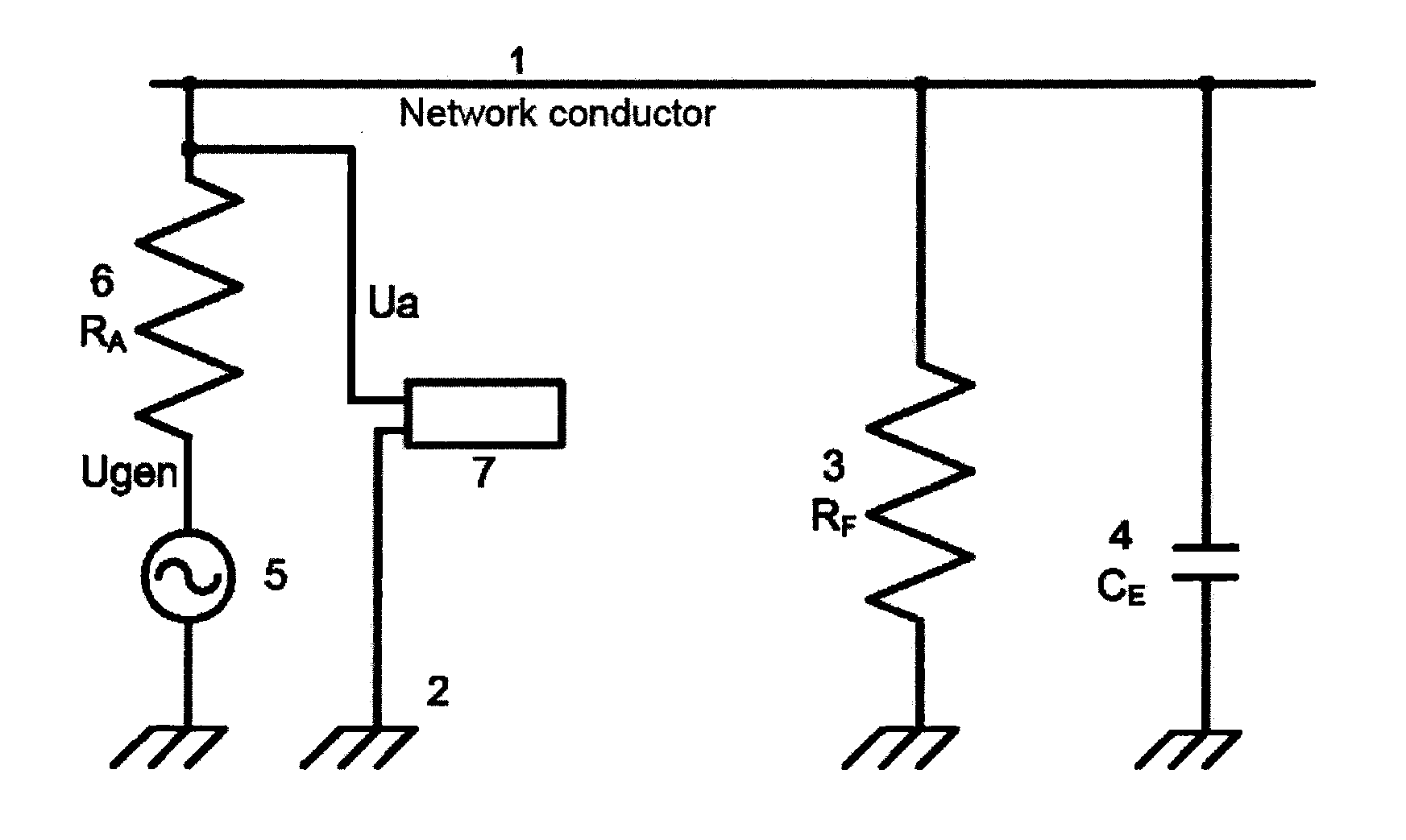
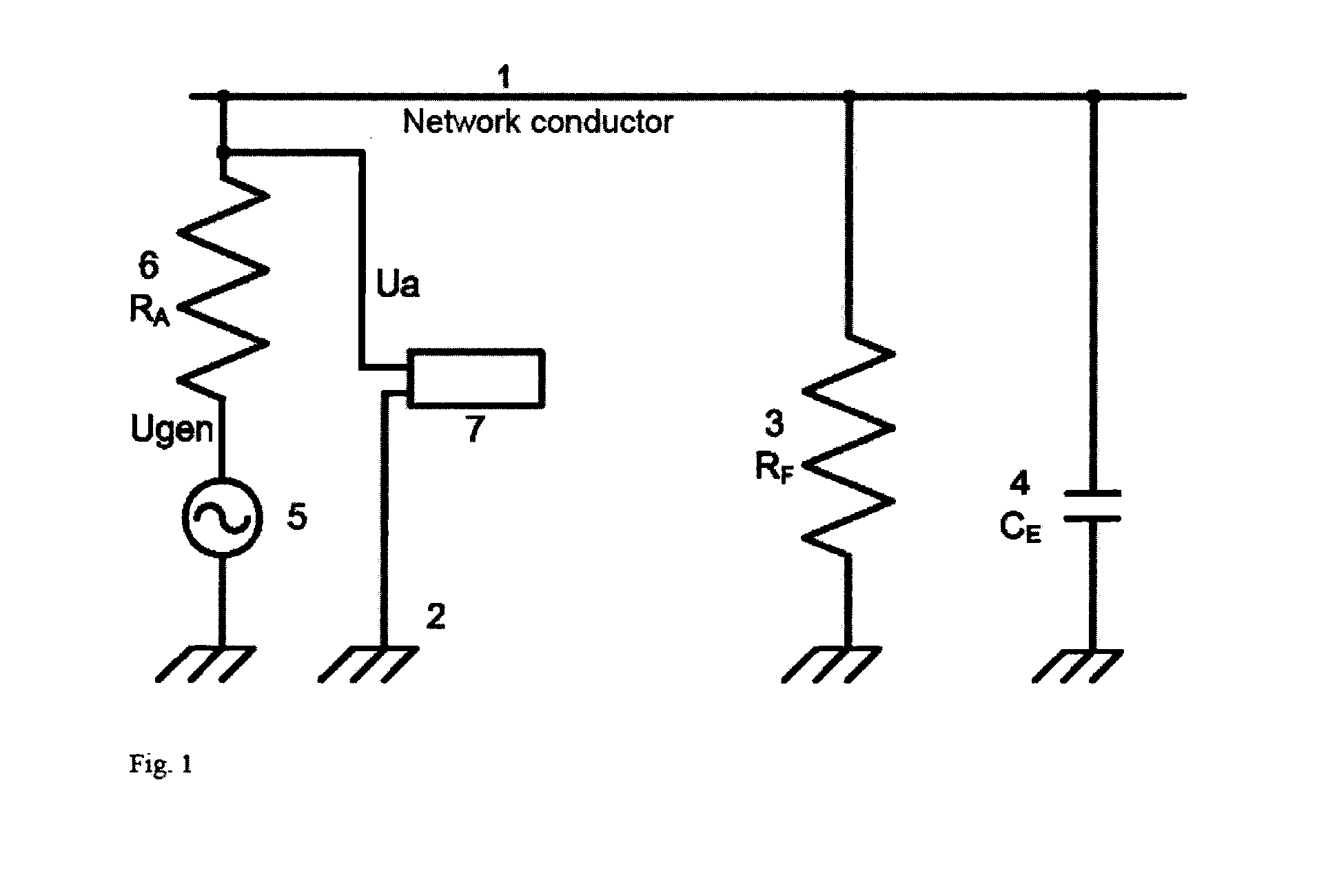
[0065]In a schematic illustration, FIG. 1 shows a network conductor 1 of a power supply system, which is connected to the ground potential 2 via a (faulty) insulation resistance RF 3 and a leakage capacity CE 4. A signal generator circuit 5 of a monitoring device, for example an insulation monitoring apparatus, generates a measuring signal Ugen (generator voltage) which is supplied to the network conductor 1 via a coupling resistance RA 6. In principle, it is also possible to couple in a current signal instead of a measuring voltage as a measuring signal, wherein then the coupling resistance RA can be omitted. Measured values of the measuring signal on the network conductor are registered by a measuring circuit 7 and used in a subsequent evaluation device to calculate the insulation resistance RF 3 and the leakage capacity CE 4.

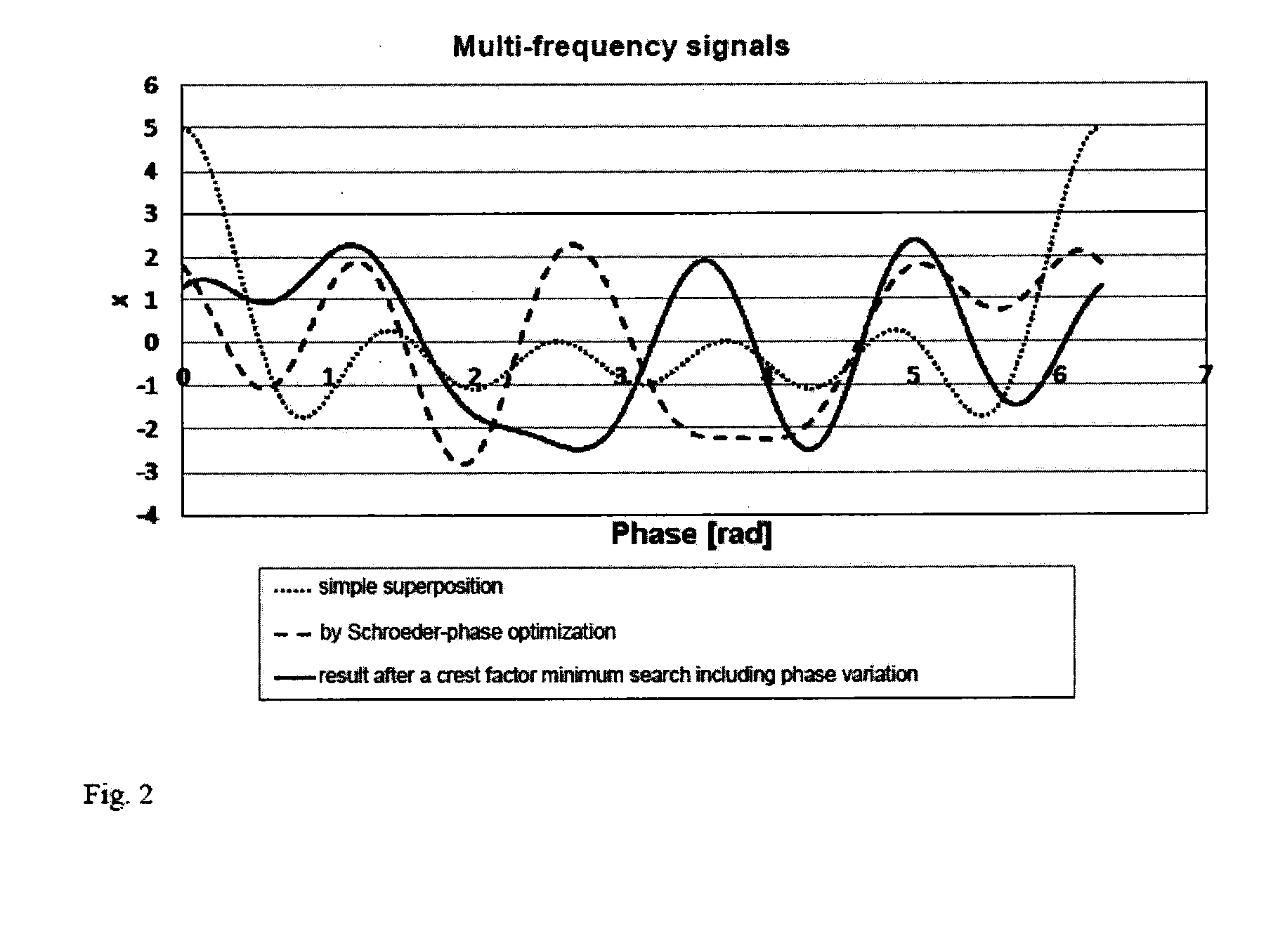
[0066]In FIG. 2, a multi-frequency signal according to the invention is illustrated. Starting from a simple superposition according to equation (1) (dotted l...


PUM


Abstract

A method for monitoring and measuring an insulation resistance in ungrounded and grounded power supply systems includes the method steps of generating a periodic measuring signal, coupling in the measuring signal between active conductors of the power supply system to be monitored and ground, and detecting and evaluating measured values of the measuring signal. In one embodiment of the invention, the generated measuring signal is formed as a multi-frequency signal by the superposition of a finite number of harmonic oscillations with at least three harmonics. Alternatively, the multi-frequency signal can also be realized by means of a targeted, portioned construction of the signal shape in the time domain on the basis of a binary sequence optimization or by generating the measuring signal by means of the time-division multiplexing method.

Description

CROSS REFERENCE TO RELATED APPLICATION[0001]This application claims the priority benefit of German Patent Application No. 10 2012 218 107.5 filed on Oct. 4, 2012, which is fully incorporated herein by reference.STATEMENT REGARDING FEDERALLY SPONSORED RESEARCH OR DEVELOPMENT[0002]Not applicable.FIELD OF THE INVENTION[0003]The invention relates to a method for monitoring and measuring an insulation resistance in ungrounded and grounded power supply systems, comprising the method steps of: generating a periodic measuring signal, coupling in the measuring signal between active conductors of the power supply system to be monitored and ground, and detecting and evaluating measured values of the measuring signal.[0004]Further, the invention relates to a signal generator for monitoring an insulation resistance in ungrounded and grounded power supply systems, comprising a signal generator circuit for generating a periodic measuring signal, and comprising a coupling circuit for coupling in th...

Claims


Application Information

Patent Timeline
Patent Type & Authority Applications(United States)
IPC IPC(8): G01R31/12
CPCG01R31/1272G01R27/025G01R27/18H02H5/105
Inventor BROECKMANN, ECKHARDMACHT, BURKHARDHACKL, DIETER
Owner BENDER SA
Why Eureka
Try Eureka