
Cache control apparatus and cache control method

a control apparatus and cache technology, applied in the field of cache control on a storage system, can solve the problems of large overhead, high dram speed, and problems in terms of increasing capacity and price, and achieve the effect of shortening the lifetime, effectively limiting the degradation of the storage part, and shortening the lifetim

Inactive Publication Date: 2014-04-24
HITACHI LTD
View PDF6 Cites 38 Cited by
  • Summary
  • Abstract
  • Description
  • Claims
  • Application Information

AI Technical Summary

Benefits of technology

The patent text is about a system that can cache data that is frequently updated in a separate storage part, which allows for faster processing. It also suggests that data that is not frequently updated can be cached in a different storage part to prevent it from becoming obsolete. This system helps in improving the performance and efficiency of a computer network.

Problems solved by technology

This is because a large overhead occurs if all possible accesses to an HDD that is a final storage place for data are made.
DRAMs are much higher in speed than HDDs but have problems in terms of increasing the capacity and in terms of price.

Method used


Image

  • Cache control apparatus and cache control method
  • Cache control apparatus and cache control method
  • Cache control apparatus and cache control method

Examples


embodiment 1

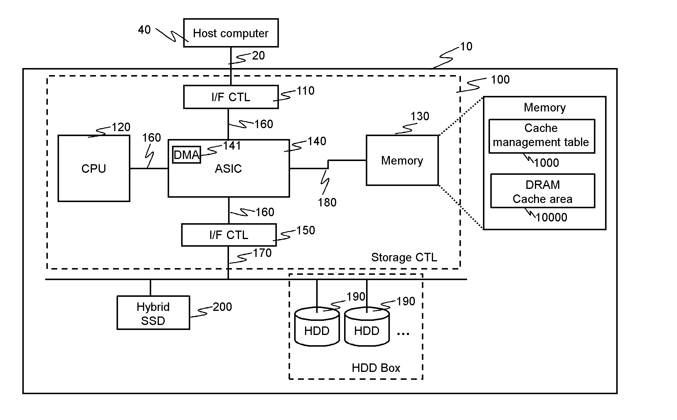
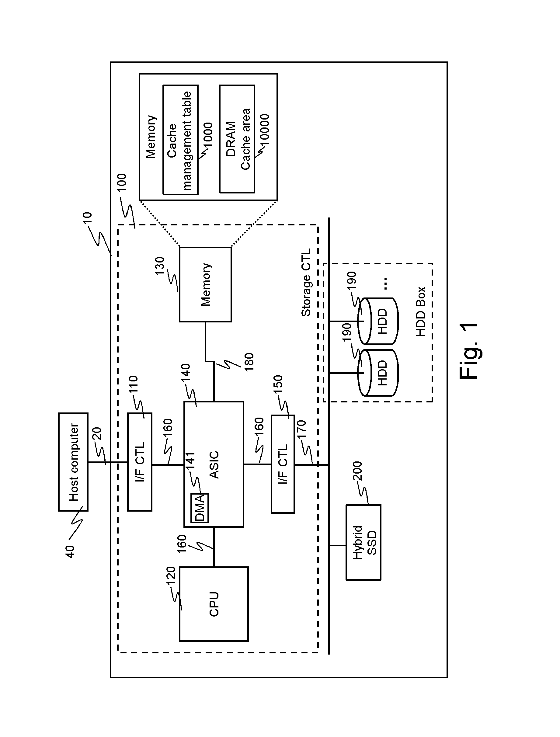
[0038]FIG. 1 is a diagram of the configuration of an example of a storage system according to Embodiment 1.

[0039]The storage system comprises a storage apparatus 10, which is an example of the cache control apparatus, and a host computer 40. The storage apparatus 10 and the host computer 40 are connected to each other through a network 20 such as a SAN (Storage Area Network) or a LAN (Local Area Network). The host computer 40 is, for example, a general-purpose computer. The host computer 40 executes a predetermined operational processing by reading out data stored in the storage apparatus 10 and storing data in the storage apparatus 10.

[0040]The storage apparatus 10 includes a storage controller 100, which is an example of a first controller, a hybrid SSD 200, which is an example of the cache control apparatus, and at least one HDD 190. The HDD 190 is used as a final storage device in which data is finally stored. The storage controller 100 is connected to the hybrid SSD 200 and to ...

embodiment 2

[0142]A storage system according to Embodiment 2 will next be described.

[0143]FIG. 19 is a diagram of the configuration of an example of a storage system according to Embodiment 2.

[0144]The storage system according to Embodiment 2 comprises an SLC SSD 220 and an MLC SSD 230 provided in place of the hybrid SSD 200 in the storage system according to Embodiment 1.

[0145]A storage apparatus 10 according to Embodiment 2 includes a storage controller 100, and the SLC SSD 220 and the MLC SSD 230 as an SSD cache (secondary cache).

[0146]The SLC SSD 220 is a device including an SLC-type NAND flash memory chip having an initial lifetime longer than that of the MLC SSD 230. The SLC SSD 220 is an example of a long-life device (second storage part). The MLC SSD 230 is a device including an MLC-type NAND flash memory chip having an initial lifetime shorter than that of the SLC SSD 220. The MLC SSD 230 is an example of a short-life device (first storage part). The configurations of the storage contr...

embodiment 3

[0157]A storage system according to Embodiment 3 will next be described.

[0158]FIG. 20 is a diagram of the configuration of an example of a storage system according to Embodiment 3.

[0159]The storage system according to Embodiment 3 has an SSD cache life management table 8000 stored in the memory 130 in the storage system according to Embodiment 2. The storage system according to Embodiment 3 also uses SSDs of the same kind (SLC SSDs 2201, 2202) having different remaining lifetimes in place of the different kinds of SSDs: SLC SSD 220 and MLC SSD 230.

[0160]Each of the SLC SSD 2201 and SLC SSD 2202 is a device including an SLC-type NAND flash memory chip. The SLC SSD 2201 has a remaining lifetime longer than that of the SLC SSD 2202. The SLC SSD 2201 is an example of a long-life device (an example of the second storage part). The SLC SSD 2202 is an example of a short-life device (an example of the first storage part).

[0161]Cache control in the storage system according to Embodiment 3 is...


PUM


Abstract

A cache control apparatus comprises a primary cache part, a secondary cache part for caching data destaged from the primary cache part, and a controller connected to the primary cache part and to the secondary cache part. The secondary cache part has a first storage part and a second storage part having a lifetime longer than that of the first storage part. The controller determines whether the data destaged from the primary cache part is to be stored in the first storage part or the second storage part in the secondary cache part, based on a use state indicating whether or not the data has been updated, and stores the data in the first storage part or the second storage part determined.

Description

TECHNICAL FIELD[0001]The present invention relates to cache control on a storage system.BACKGROUND ART[0002]In recent years, SSDs (Solid State Drives) using a semiconductor device as a storage medium have been increasingly used in storage systems. SSDs are superior in random access performance to conventional HDDs. Schemes to develop SSDs larger in capacity and lower in price as SSDs using NAND flash memories in particular have progressed and the replacement of HDDs with such SSDs is now in progress. SCMs (Storage Class Memories) as a nonvolatile storage medium are smaller in capacity and higher in price than NAND flash memories but have higher access speeds and can be rewritten a larger number of times and are, therefore, attracting attention as a high-performance long-life recording medium. SCMs are a kind of nonvolatile semiconductor memory, e.g., an MRAM (Magnetic Random Access Memory), a PRAM (Phase Change Random Access Memory) and a ReRAM (Resistance Random Access Memory).[000...

Claims


Application Information

Patent Timeline
Patent Type & Authority Applications(United States)
IPC IPC(8): G06F12/08G06F12/02G06F12/0811G06F12/0868G06F12/0897
CPCG06F12/0246G06F12/0811G06F12/0868G06F12/0897G06F2212/225G06F2212/7208
Inventor ITO, YUJIOGAWA, JUNJIKOSEKI, HIDEYUKI
Owner HITACHI LTD
Learn More