
Connector Apparatus for Flat Blade-Type Wiper

Inactive Publication Date: 2014-05-01
TOYO KIDEN
View PDF3 Cites 2 Cited by
  • Summary
  • Abstract
  • Description
  • Claims
  • Application Information

AI Technical Summary

Benefits of technology

The present invention provides a connector apparatus for a flat blade-type wiper that improves assembly by being easily detached from a vertebra that supports a wiper lip, makes management of post easier by being easily separated, and reduces the cost burden on consumers.

Problems solved by technology

As conditions of expressways have been improved and performances of vehicles have been improved in recent years, problems of a conventional blade assembly for cleaning a windscreen of a vehicle have been pointed out.
That is, when a wiper operates while a vehicle is running at a high speed of 160 km / hour or more, a lift force may be applied to the conventional blade assembly and thus the conventional blade assembly may not correctly contact a windscreen of the vehicle, thereby failing to remove foreign substances or rainwater.
Accordingly, the conventional connector apparatus coupled to the vertebra may not be able to be physically separated from the vertebra.
Since the conventional connector apparatus may not be able to be separated from the vertebra when the connector apparatus needs to be exchanged while a wiper apparatus is being used, it is inconvenient to use the conventional connector apparatus.
Also, when the conventional connector apparatus is broken, a consumer has to exchange the entire wiper apparatus, thereby increasing exchange costs.
Also, since the conventional connector apparatus has to be cocked or bent during an assembly process, assemblability is poor.

Method used


Image

  • Connector Apparatus for Flat Blade-Type Wiper
  • Connector Apparatus for Flat Blade-Type Wiper
  • Connector Apparatus for Flat Blade-Type Wiper

Examples


Embodiment Construction

[0019]The present invention will now be described more fully with reference to the accompanying drawings, in which exemplary embodiments of the invention are shown.

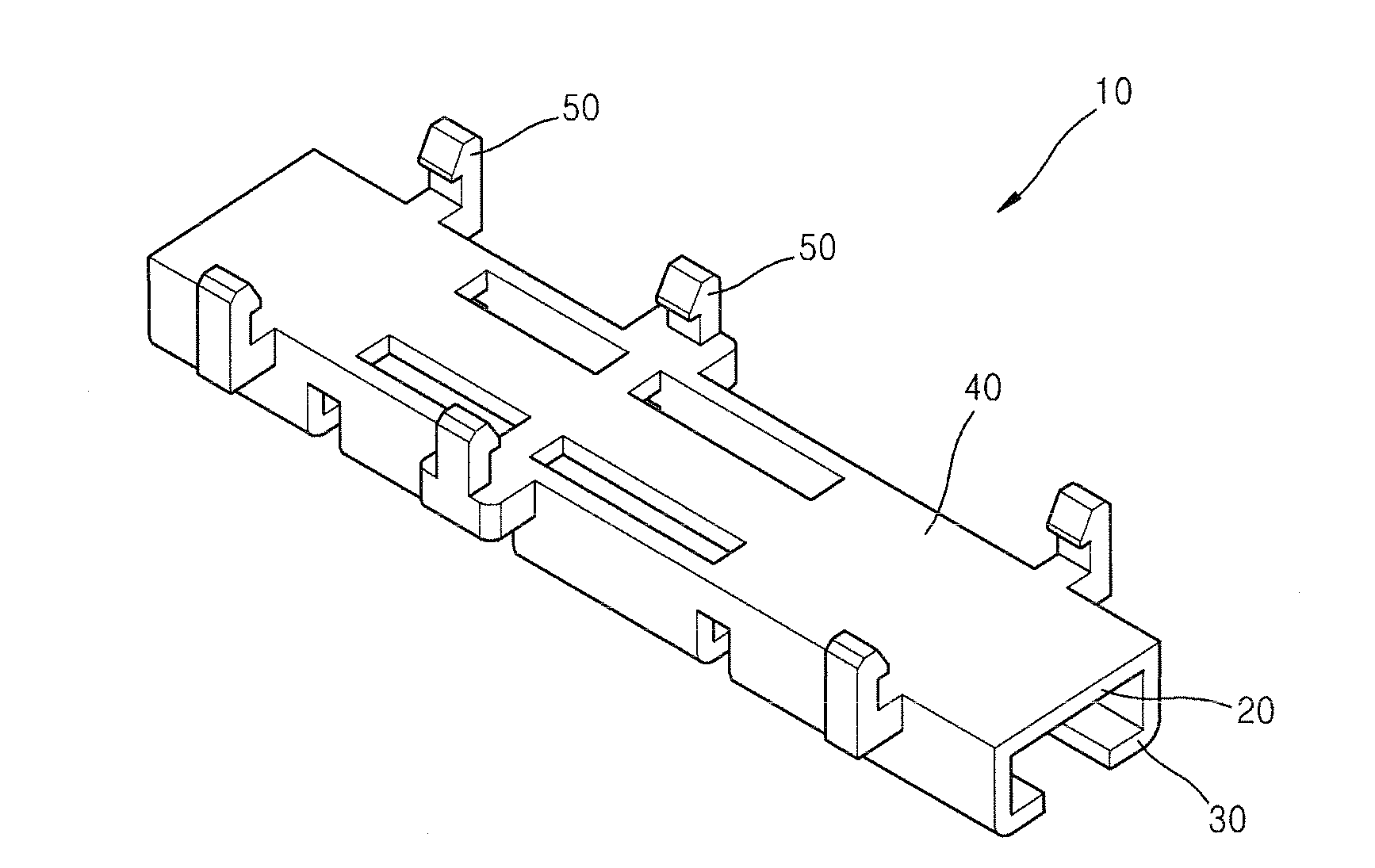
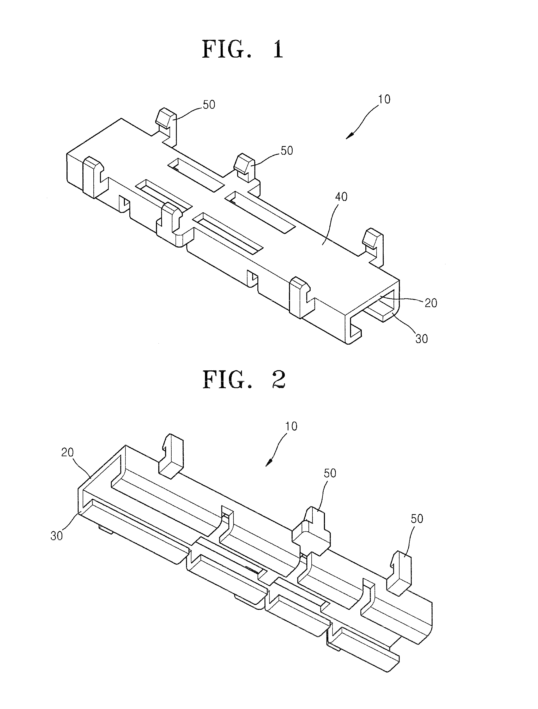
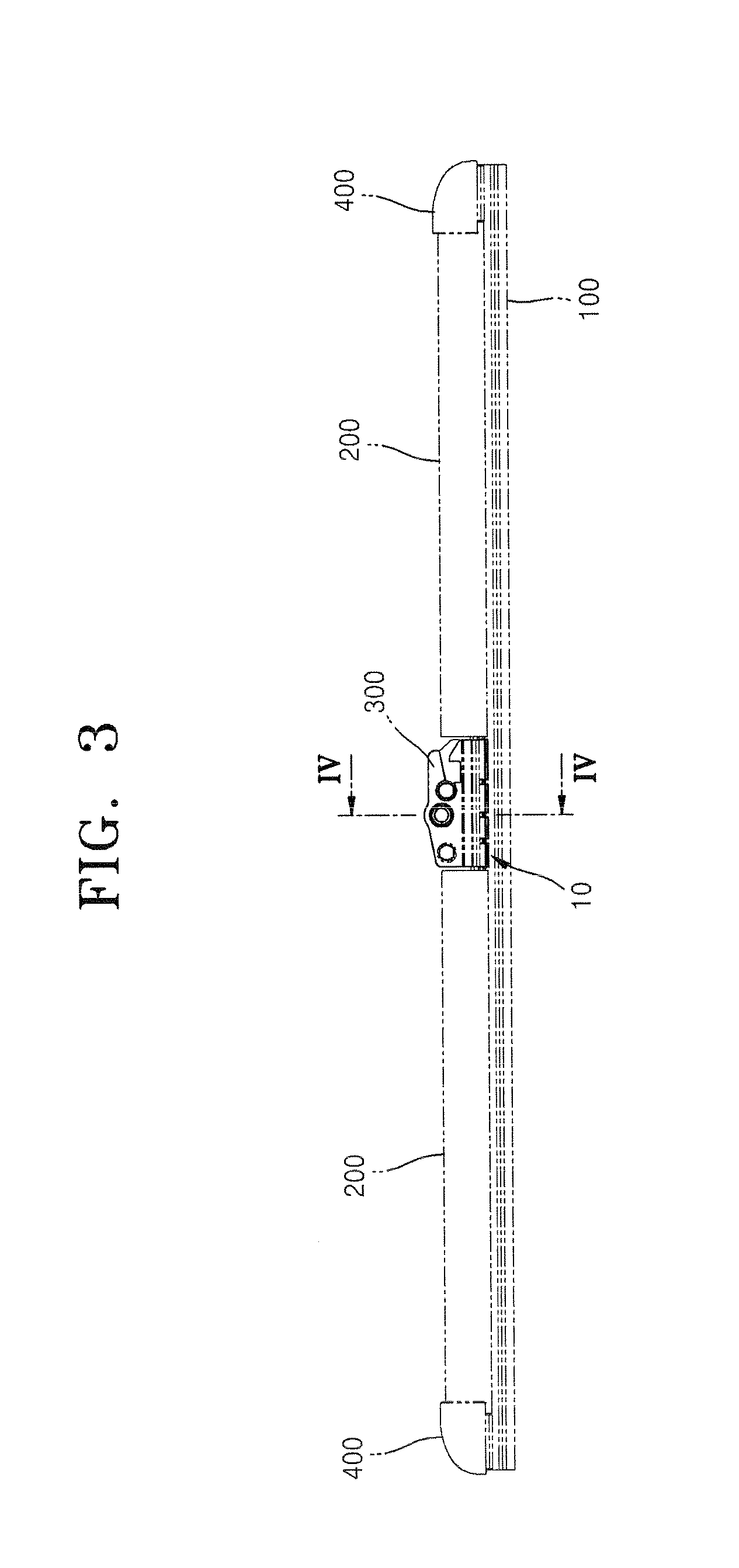
[0020]FIG. 1 is a perspective view illustrating a connector apparatus for a flat blade-type wiper, according to an embodiment of the present invention. FIG. 2 is a perspective view illustrating a lower structure of the connector apparatus of FIG. 1. FIG. 3 is a side view illustrating the flat blade-type wiper employing the connector apparatus of FIG. 1. FIG. 4 is a cross-sectional view taken along line IV-IV of FIG. 3. FIG. 5 is an enlarged view illustrating a structure of the flat blade-type wiper employing the connector apparatus of FIG. 1.

[0021]Referring to FIGS. 1 through 5, a connector apparatus 10 for a flat blade-type wiper (hereinafter, referred to as a “connector apparatus”) according to an embodiment of the present invention is disposed at a central portion in a longitudinal direction of a flat blade-type wiper....


PUM


Abstract

Provided is a connector apparatus for a flat blade-type wiper. The connector apparatus is disposed at a central portion in a longitudinal direction of the flat blade-type wiper. The connector apparatus includes: a body: a wiper lip receiving guide unit that is disposed under the body and includes a bottom portion open in order to receive an upper end portion of a wiper lip and both ends having hook shapes; a vertebra receiving unit that is disposed on a top surface of the body and receives therein a vertebra that elastically supports the wiper lip; and elastic hook units that protrude upward from both sides of the vertebra receiving unit, each have a hook-shaped structure formed on an upper end portion, and elastically partially support top surfaces of both sides of the vertebra received in the vertebra receiving unit.

Description

CROSS-REFERENCE TO RELATED PATENT APPLICATION[0001]This application claims the benefit of Korean Patent Application No. 10-2012-0119301, filed on Oct. 25, 2012, in the Korean Intellectual Property Office, the disclosure of which is incorporated herein in its entirety by reference.BACKGROUND OF THE INVENTION[0002]1. Field of the Invention[0003]The present invention relates to a wiper blade apparatus for a vehicle, and more particularly, to a flat blade-type wiper apparatus.[0004]2. Description of the Related Art[0005]In general, a blade assembly for cleaning a windscreen of a vehicle is an active safety device as well as an assistance device provided to clear a driver's view by removing foreign substances or rainwater from a surface of a front windscreen of the vehicle.[0006]In general, a blade assembly for cleaning a windscreen of a vehicle includes a wiper strip that slidably contacts the windscreen of the vehicle and is formed of elastic rubber, a vertebra that elastically support...

Claims


Application Information

Patent Timeline
IPC IPC(8): B60S1/38
CPCB60S1/3849B60S1/3858B60S1/34B60S1/40
Inventor PARK, WI YEONGYOON, SUNG JUN
Owner TOYO KIDEN
Learn More