Single channel scanning acoustic microscope with multiple focused ultrasonic transducers

a scanning acoustic microscope and focused ultrasonic technology, applied in the field of single channel scanning acoustic microscopes, can solve the problems of limiting the scanning speed of the x-y driver system, affecting the accuracy of the scanning results,

Active Publication Date: 2014-05-01
NORDSON CORP
View PDF8 Cites 12 Cited by
  • Summary
  • Abstract
  • Description
  • Claims
  • Application Information

AI Technical Summary

Problems solved by technology

Its throughput is largely limited by two factors.
One limiting factor is the scanning speed of the X-Y driver system that moves the ultrasonic transducer with respect to the part or sample being inspected.
Unfortunately, at high frequencies pulse generation technology is very close to the achievable limits of PRF.
However, the multi-channel approach is ve

Method used


Image

  • Single channel scanning acoustic microscope with multiple focused ultrasonic transducers
  • Single channel scanning acoustic microscope with multiple focused ultrasonic transducers
  • Single channel scanning acoustic microscope with multiple focused ultrasonic transducers

Examples


Embodiment Construction

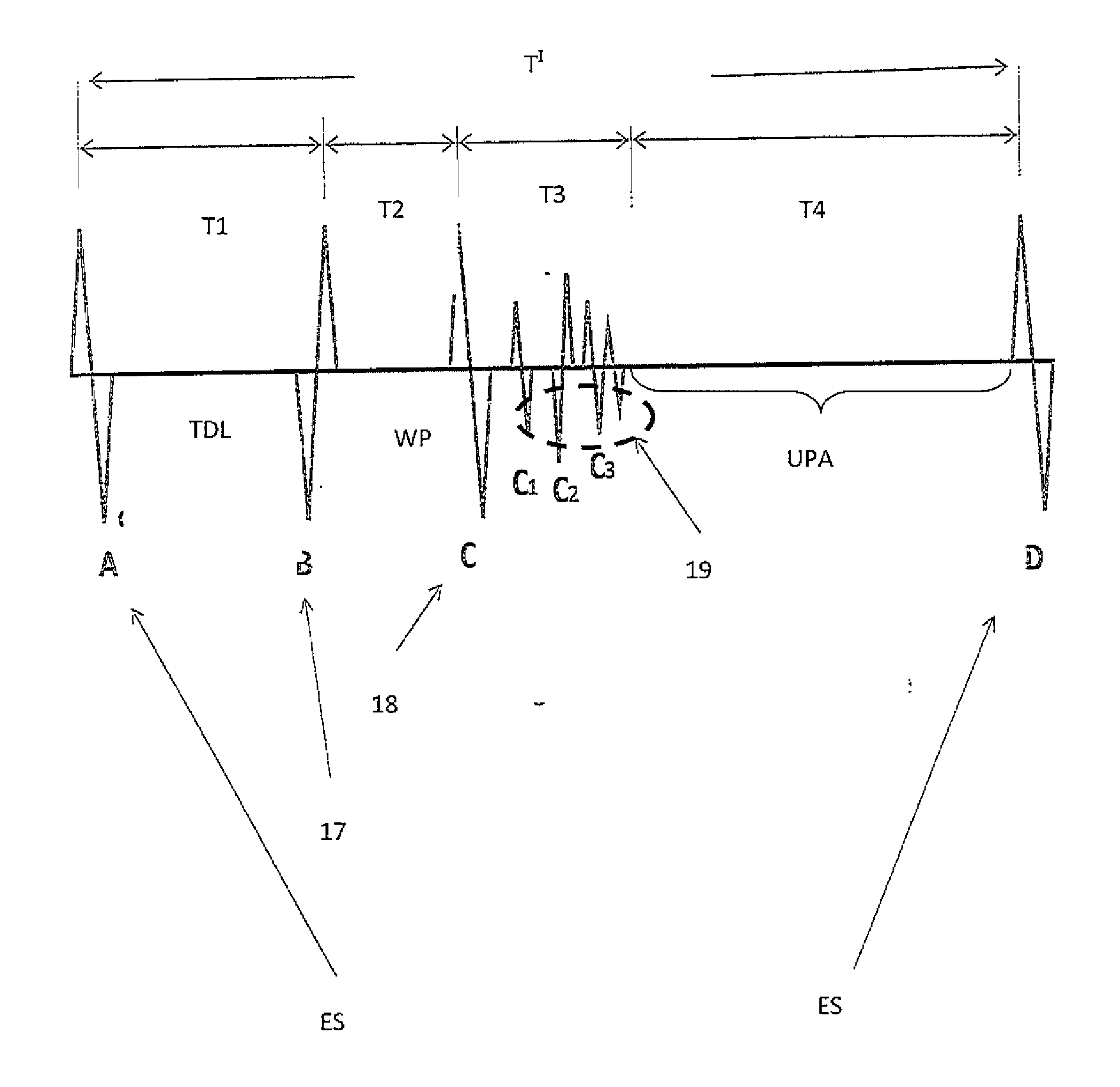
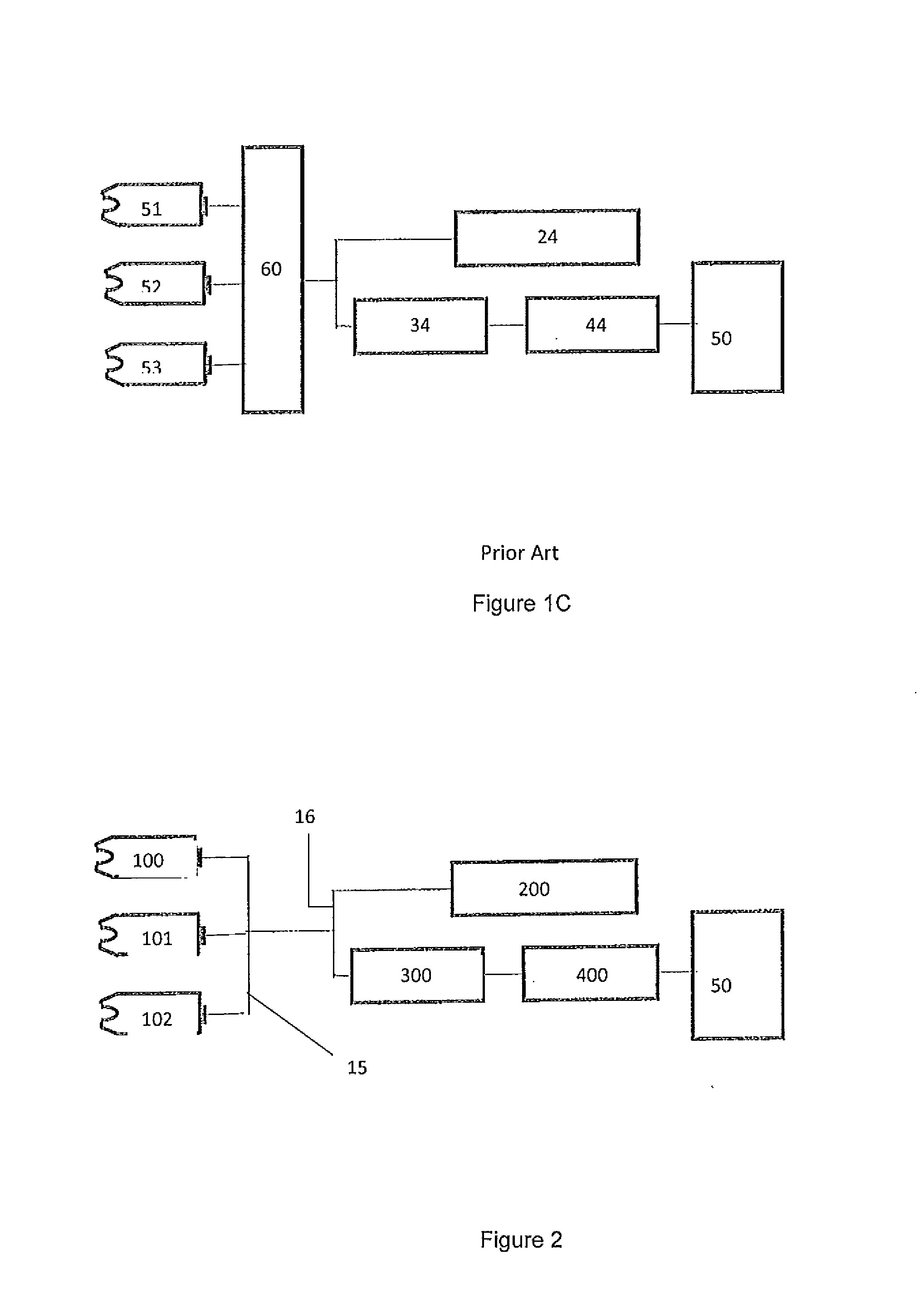
[0029]The purpose of this invention is to increase the throughput of the acoustic imaging system by connecting a multi-transducer assembly 15“in parallel” to a single channel electronic circuit 16 as, for example, shown in FIG. 2. The multi-transducer assembly 15 comprises transducers 100-102 and the single channel electronic circuit 16 comprises a transducer 10, a pulser 200, an amplifier 300, a digital converter 400 and a visual display, such as a monitor 50. This configuration has numerous advantages when compared with the prior art connections described in FIGS. 1A, 1B and 1C,

[0030]The single channel electronic system 16, without multiplexing, does not reduce the pulse repletion rate and, as a result, will not lower the scan resolution or scanning speed. On the other hand, this system has a substantially lower cost when compared with the multi-channel systems since it requires a single electronic channel.

[0031]In order to display and process the ultrasonic signals from multiple ...


PUM


Abstract

A single channel scanning acoustic microscope that increases the throughput of the acoustic imaging system by connecting a multi-transducer assembly in parallel to a single channel electronic circuit. The single channel scanning acoustic microscope includes multiple transducers configured to generate a time delay for individual ultrasonic waves generated by each transducer, wherein a pulse generator simultaneously sends a pulse signal to the multi-transducer assembly.

Description

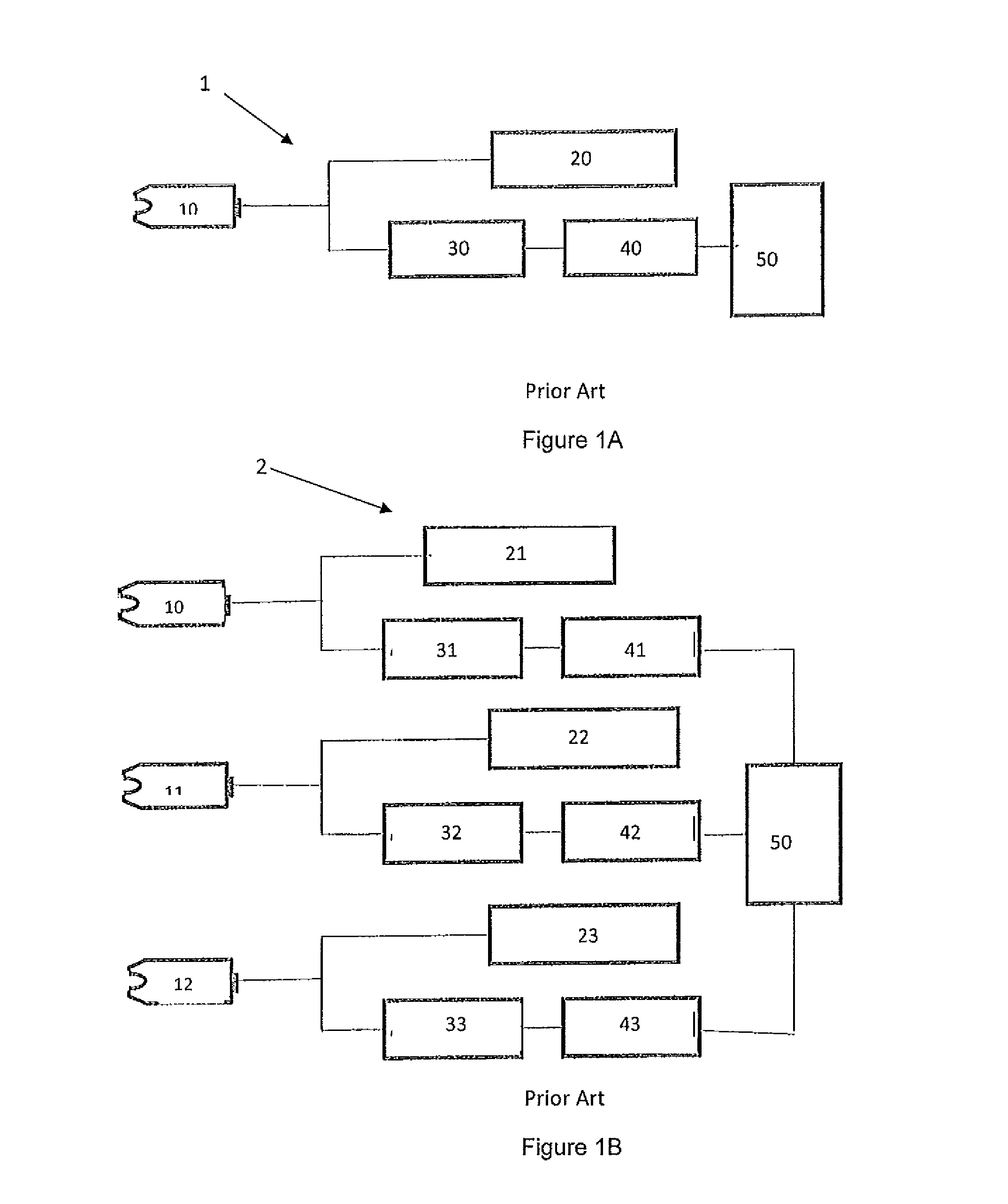
RELATED APPLICATIONS [0001]This application claims the benefit of U.S. Provisional Application No. 61 / 795,873 filed Oct. 26, 2012, which is hereby incorporated by reference in its entirety.STATEMENT REGARDING FEDERALLY SPONSORED RESEARCH AND DEVELOPMENT[0002]N / ABACKGROUND OF THE DISCLOSUREField of the Disclosure[0003]The present invention relates to a single channel scanning acoustic microscope which uses multiple focused ultrasonic transducers.Discussion of the Background[0004]The effectiveness of any non-destructive inspection, evaluation methodology and acoustic imaging methodology depends particularly on the throughput of the inspection system. Referring to FIG. 1A, a prior art acoustic imaging system with a single focused transducer 1 is shown. The acoustic imaging system with a single focused transducer 1 comprises a transducer 10, a pulser 20, an amplifier 30, a digital converter 40 and a visual display, such as a monitor 50. Its throughput is largely limited by two factors. ...

Claims


Application Information

Patent Timeline
IPC IPC(8): G01N29/26G01N29/34
CPCG01N29/26G01N29/34G01N29/0681G01N29/262G01N29/28G01N29/341G01N29/343
Inventor KOMSKY, IGOR N.KESSLER, LAWRENCE W.
Owner NORDSON CORP
Why Eureka
Try Eureka