
Device and method for determining and controlling combustion misfire of vehicle engine

a technology of combustion misfire and engine, which is applied in the direction of combustion engines, electric control, machines/engines, etc., can solve the problems of non-normal combustion, non-uniform engine torque, and misfire generated without normal combustion, so as to prevent deterioration of stability of operating a vehicle, accurate determination of misfire in real time, and reduction of fuel efficiency

Inactive Publication Date: 2014-05-01
HYUNDAI MOTOR CO LTD
View PDF16 Cites 5 Cited by
  • Summary
  • Abstract
  • Description
  • Claims
  • Application Information

AI Technical Summary

Benefits of technology

The present invention provides a method and control device for detecting and controlling misfire in a combustion chamber of an engine. By sensing combustion pressure, misfire can be accurately determined in real time and controlled by advancing fuel injection time. This prevents misfire from causing stability and riding comfort issues and reduces harmful exhaust gas discharge and fuel inefficiency.

Problems solved by technology

In general, in a vehicle engine, misfire is generated without normal combustion in the cylinders of the engine due to an ignition failure, a defect in a fuel supply system, a pressure decrease of fuel, or other reasons.
Misfire during combustion in an engine causes a loss of power from the engine and a non-uniform engine torque, such that a vibration or noise is generated from the engine.
The misfire in an engine means all processes where a flame is not propagated around an ignition source even though an igniter ignites a mixture of fuel and air mixed in a combustion chamber in an engine, where a flame is only partially propagated even if there is a propagation of flame, or where the propagation speed of a flame is irregular or an abnormal combustion is generated by speed delay Misfire contaminates the environment by increasing noxious gases that are exhausted, in addition to damaging the engine and the exhaustion system for exhaustion gases, depending on the state of the misfire.

Method used


Image

  • Device and method for determining and controlling combustion misfire of vehicle engine
  • Device and method for determining and controlling combustion misfire of vehicle engine
  • Device and method for determining and controlling combustion misfire of vehicle engine

Examples


Embodiment Construction

[0024]Exemplary embodiments of the present disclosure will now be described hereafter in detail with reference to the accompanying drawings.

[0025]Referring to FIG. 3, a device for controlling misfire in an engine (e.g., of a vehicle) according to an exemplary embodiment of the present disclosure includes a combustion pressure detecting sensor that is disposed on a cylinder head defining a combustion chamber of an engine and senses combustion pressure in the combustion chamber. The combustion pressure detecting sensor may be disposed on a glow plug mounted on the cylinder head of the engine.

[0026]Further, an injector that injects fuel into the combustion chamber is included.

[0027]The injector is connected to an output terminal of an ECU (Electronic Control Unit), and the ECU controls the injection time of fuel to be injected into the combustion chamber from the injector.

[0028]The combustion pressure detecting sensor is connected to an input terminal of the ECU to notify the ECU of th...


PUM


Abstract

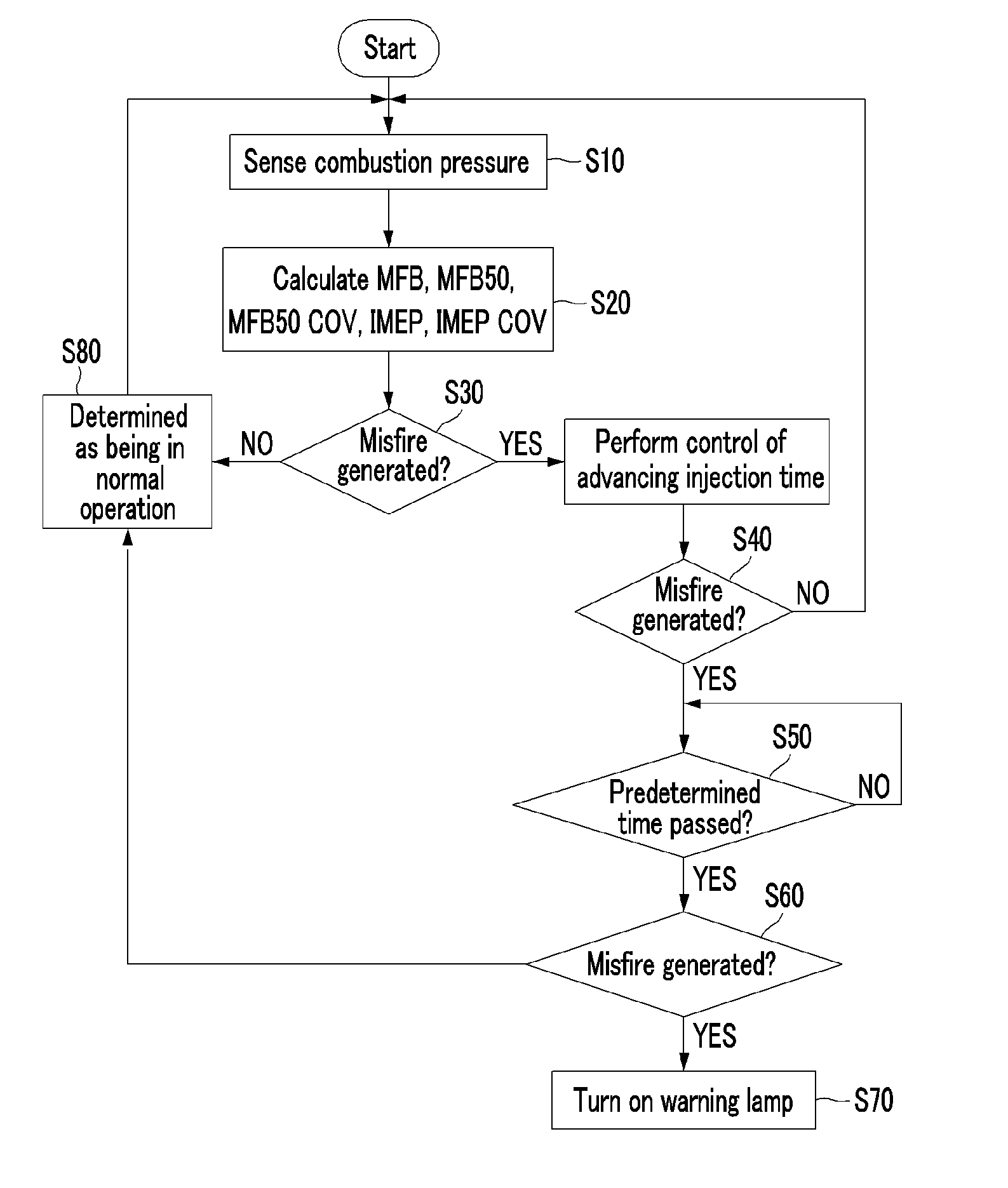
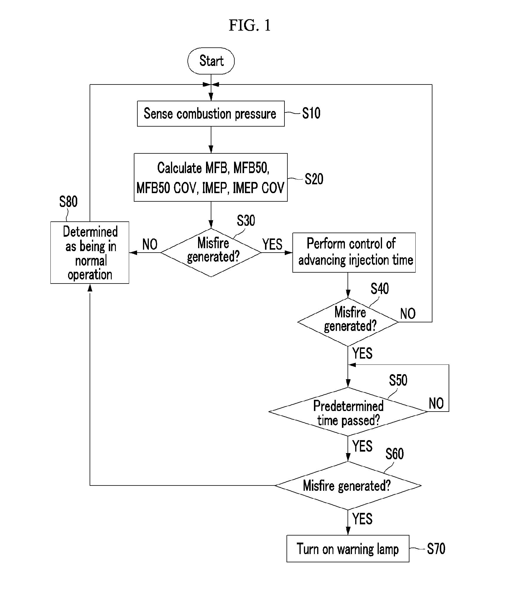
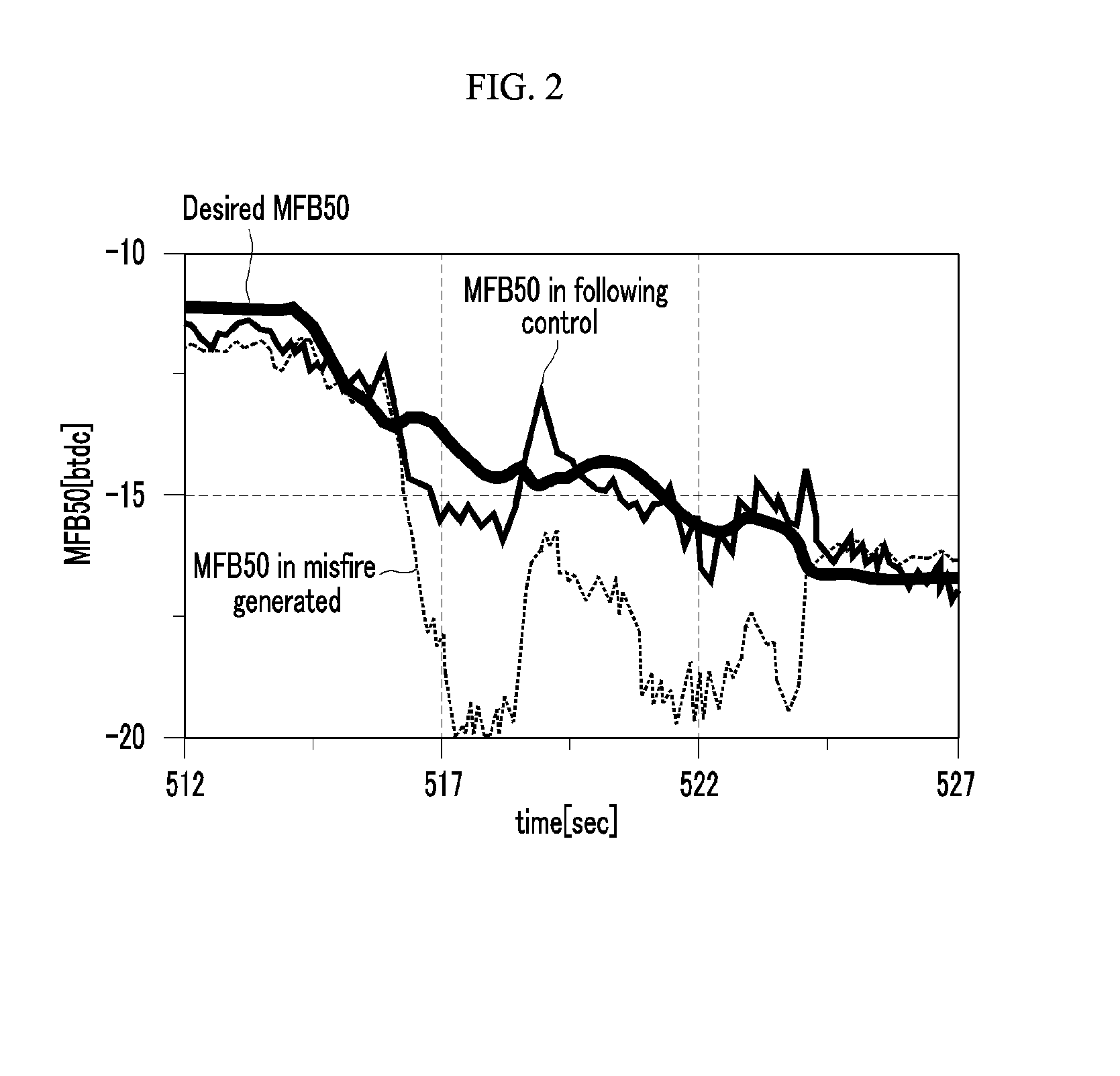
A method of determining and controlling misfire in an engine. The method and device sense combustion pressure in a combustion chamber of an engine while the engine is operated; calculate MFB (a ratio of the amount of combustion heat at a specific point of time to the total amount of combustion heat), MFB50 (a point of time at which the amount of combustion heat is 50% of the total amount of combustion heat), MFB50 COV (Coefficient of Variation), IMEP (Indicated Mean Effective Pressure) and IMEP COV, from the combustion chamber; set a desired MFB50; and determine that there is misfire when a crank angle is delayed at 5 degrees or more, the MFB50 COV is 20% or more, or the IMEP COV is 20% or more, by comparing the calculated MFB50 with the desired MFB50; and then advance an injection time such that the MFB follows the desired MFB.

Description

CROSS-REFERENCE TO RELATED APPLICATION[0001]This application claims priority to and the benefit of Korean Patent Application No. 10-201 2-01 21 391 filed in the Korean Intellectual Property Office on Oct. 30, 2012, the entire contents of which are incorporated herein by reference.BACKGROUND OF THE DISCLOSURE[0002](a) Field of the Disclosure[0003]The present disclosure relates to a method of determining and controlling combustion misfire of an engine (e.g., of a vehicle), and a control device thereof. More particularly, the present disclosure relates to a method of determining and controlling combustion misfire of a vehicle engine which determines misfire by sensing combustion pressure of the engine and controls misfire by advancing a fuel injection time, and a control device thereof.[0004](b) Description of the Related Art[0005]In general, in a vehicle engine, misfire is generated without normal combustion in the cylinders of the engine due to an ignition failure, a defect in a fuel...

Claims


Application Information

Patent Timeline
IPC IPC(8): F02D41/32
CPCF02D41/32F02D35/025F02D35/028F02D41/401F02D2041/228F02D2200/1015G01M15/11Y02T10/40F02D35/00F02D41/22F02D45/00
Inventor KIM, MINSUYU, JUNKIM, HYUNGMINHAN, KYOUNGCHAN
Owner HYUNDAI MOTOR CO LTD
Learn More