
Steering control system and method for manual wheelchairs

Inactive Publication Date: 2014-05-01
DYNAMIC CONTROLS
View PDF4 Cites 9 Cited by
  • Summary
  • Abstract
  • Description
  • Claims
  • Application Information

AI Technical Summary

Benefits of technology

This patent is about a system and method that helps wheelchair users better control the steering of their wheelchair without getting distracted from driving. This makes it easier for them to maneuver around objects without stopping or using more force. It also makes wheelchair movement more efficient, reducing strain on the user and lessening the chance of chronic injury.

Problems solved by technology

Manual wheelchairs are particularly difficult to propel in a straight line along a surface that has a camber.
The difficulty to propel occurs because front mounted castors provide no lateral stability.
This is very energy wasteful and strength sapping and can eventually be injurious to health through over-use of the shoulders and arms.
This can impair straight-line travel even on flat surfaces.
This is again energy wasteful.
Manual wheelchairs do not provide the ability of the user to easily steer around objects without either braking or drive effort.
A further disadvantage occurs when down-hill steering which, if being directed in a straight line is effortless but, if on a camber requires the user to brake and control the speed of the wheelchair using both side wheels and therefore both hands resulting in excessive energy usage.
Commonly, long-term manual wheelchair users suffer from chronic wrist, arm and shoulder injury which can eventually prevent them from using manual wheelchairs and so forcing them to move to power chairs.
By doing so, these users lose a degree of independence as well as the health benefits of exercise.
Although there are numerous patents that describe mechanical hand-operated steering devices for manual wheelchairs such as, U.S. Pat. No. 42,2620, U.S. Pat No. 479,407, U.S. Pat. No. 986,723 and EP1627619, none of these provide an electromechanical means of controlling the steering.

Method used


Image

  • Steering control system and method for manual wheelchairs
  • Steering control system and method for manual wheelchairs
  • Steering control system and method for manual wheelchairs

Examples


first embodiment

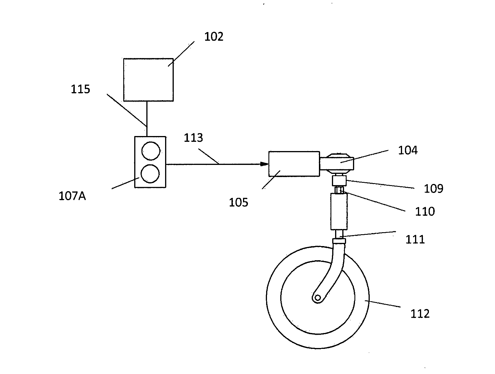
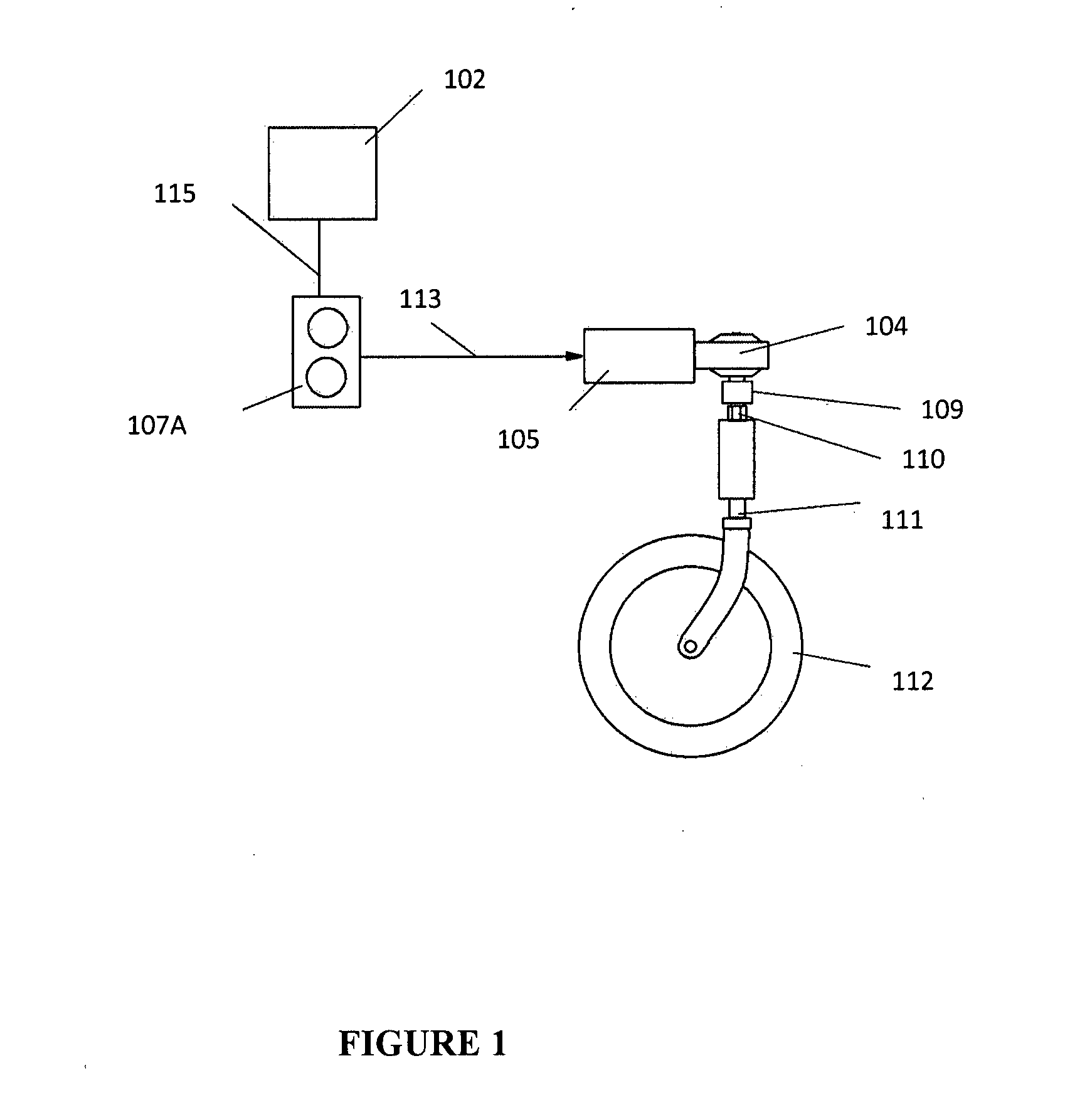
[0029]FIG. 1 shows a schematic diagram of an electro-mechanical steering system including various components according to a first embodiment. According to FIG. 1, a caster wheel 112 of a manually operated wheelchair is shown. The caster wheel 112 is connected to the body of the wheelchair via a king pin 111. A drive nut 110 is in communication with the king pin 111 and a drive socket 109 is in communication with the drive nut 110.

[0030]On top of the drive socket is located and attached thereto a gearbox 104. Any suitable gearbox may be implemented. For example, the gearbox may be a high ratio worm gearbox. As a further example, the gearbox may be a self locking gearbox that holds its rotational position when the motor is disconnected from the battery or power supply. It will be understood that battery energy consumption may therefore be reduced.

[0031]A motor 105 drives the gearbox 104. Therefore, the motor provides a direct drive mechanism for controlling the caster wheel position.

[...

second embodiment

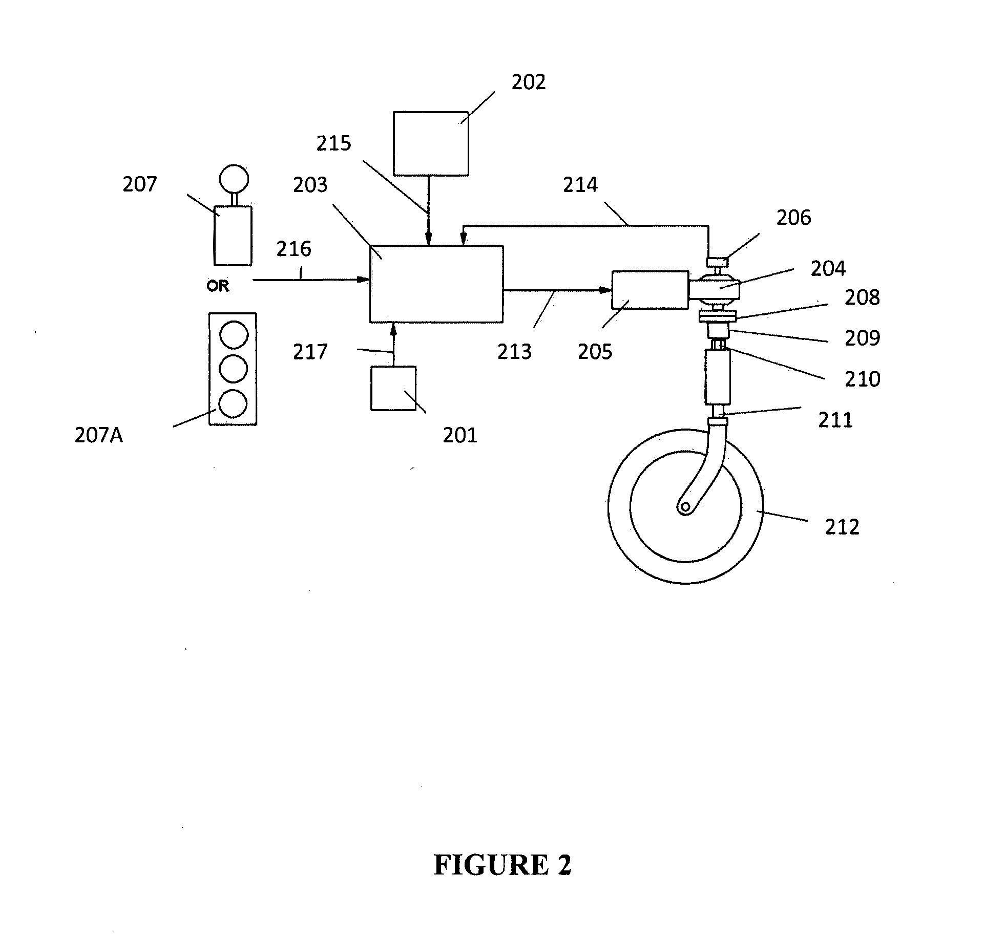
[0044]FIG. 2 shows a schematic diagram of an electro-mechanical steering system according to this second embodiment.

[0045]As described above in the first embodiment a similar arrangement of a caster wheel 212, king pin 211, drive nut 210 and drive socket 209 are provided along with a motor 205 and gearbox 204.

[0046]According to this embodiment, a clutch mechanism 208 is provided in between the gearbox 204 and drive socket 209. The clutch enables the drive from the motor to be selectively disconnected or disengaged from the caster wheel and so enables the steering control system to be temporarily disengaged from controlling the wheel position. When the clutch is re-engaged, full control of the steering system is then provided. According to this embodiment, the clutch is operated manually by the user in order to connect and disconnect the motor drive from the caster wheel. The clutch may be manually operated by the use of a switch, lever or pedal.

[0047]In addition, according to this e...

third embodiment

[0072]FIG. 4 shows a schematic diagram of an electro-mechanical steering device according to a third embodiment. The same reference numerals as shown in FIG. 2 are shown in this figure where they apply to the same component or signal.

[0073]According to this embodiment, the same system as described in the second embodiment is used except that the system does not incorporate a gyroscopic device to provide a vertical axis rotational signal. Therefore, the system is not able to automatically steer the device without receiving user input, but it is still able to monitor the actual position of the caster wheel via the steering feedback signal from the angular feedback device.

[0074]In order to provide an indication of the problem associated with manual wheelchairs travelling on a camber, FIG. 6 shows a view of a wheelchair travelling on a camber 601.

[0075]FIG. 7 shows an indication of the travel path of the wheelchair along a surface 701 when there is no adjustment of steer 703, and where ...


PUM


Abstract

An electromechanical steering system for attachment to a manually operated wheelchair, the electromechanical steering system including: an input device arranged to develop an input signal, a motor and a wheel steering system driven by the motor and arranged to communicate with a wheel of the manually operated wheelchair to adjust a steering direction of the wheel based on the input signal.

Description

FIELD OF THE INVENTION[0001]The present invention relates to a steering control system and method for manual wheelchairs. In particular, the present invention relates to a steering control system and method for manual wheelchairs that controls the steering direction of at least one wheel of the wheelchair.BACKGROUND[0002]Manual wheelchairs are particularly difficult to propel in a straight line along a surface that has a camber. This is especially true where the wheelchair is set up with its weight forward to improve stability and safety. The difficulty to propel occurs because front mounted castors provide no lateral stability. On cambers a wheelchair will naturally tend to pivot about the vertical axis of its rear axles and via down the camber.[0003]In order to correct this motion the user must apply braking to the uppermost wheel and extra drive to the lower wheel to maintain direction and speed. This is very energy wasteful and strength sapping and can eventually be injurious to...

Claims


Application Information

Patent Timeline
IPC IPC(8): B62D5/04
CPCB62D5/0421A61G5/04A61G2203/14A61G2203/36A61G5/1051
Inventor PETTIGREW, WARREN GORDONPALMER, IAN
Owner DYNAMIC CONTROLS
Learn More