
Conveyor system wear indication devices and methods

a conveyor system and wear indication technology, applied in the direction of conveyor control devices, conveyor parts, packaging, etc., can solve the problems of reduced conveying capability, inefficiency, lost time, and track wear, so as to reduce the cost, reduce the cost, and reduce the effect of conveying capacity

Active Publication Date: 2014-05-01
SOLUS INDAL INNOVATIONS
View PDF7 Cites 20 Cited by
  • Summary
  • Abstract
  • Description
  • Claims
  • Application Information

AI Technical Summary

Benefits of technology

The patent text describes the difficulty of determining the wear of a track while the conveyor system is operating. This can result in slowed or stopped conveyor systems to conduct accurate inspections, which may be inconvenient and costly. The technical effect of this patent is to provide a way to determine the level of wear on the track by conducting a visual inspection of the conveyor and track during normal operation, without the need for slowing or stopping the conveyor. This can help to prevent decreased performance or failure of the conveyor system and reduce lost time and cost.

Problems solved by technology

Over time, the track may begin to wear due to the friction between the track and the conveyor.
However, the wear of the track can be difficult to determine (e.g., observe, measure, or otherwise discern) while the conveyor system is operating.
This can be inconvenient and can result in a reduction of conveying capability, inefficiency, lost time, and increased cost.
Nevertheless, determining the level of wear on the track can be desirable and / or important because elevated levels of wear can lead to decreased performance or even failure of the conveying system.
This can be inconvenient, as it requires locating and using those instruments.
Moreover, the measurement itself may not provide an indication of whether the amount of wear is still within a recommended or permissible range.

Method used


Image

  • Conveyor system wear indication devices and methods
  • Conveyor system wear indication devices and methods
  • Conveyor system wear indication devices and methods

Examples


Embodiment Construction

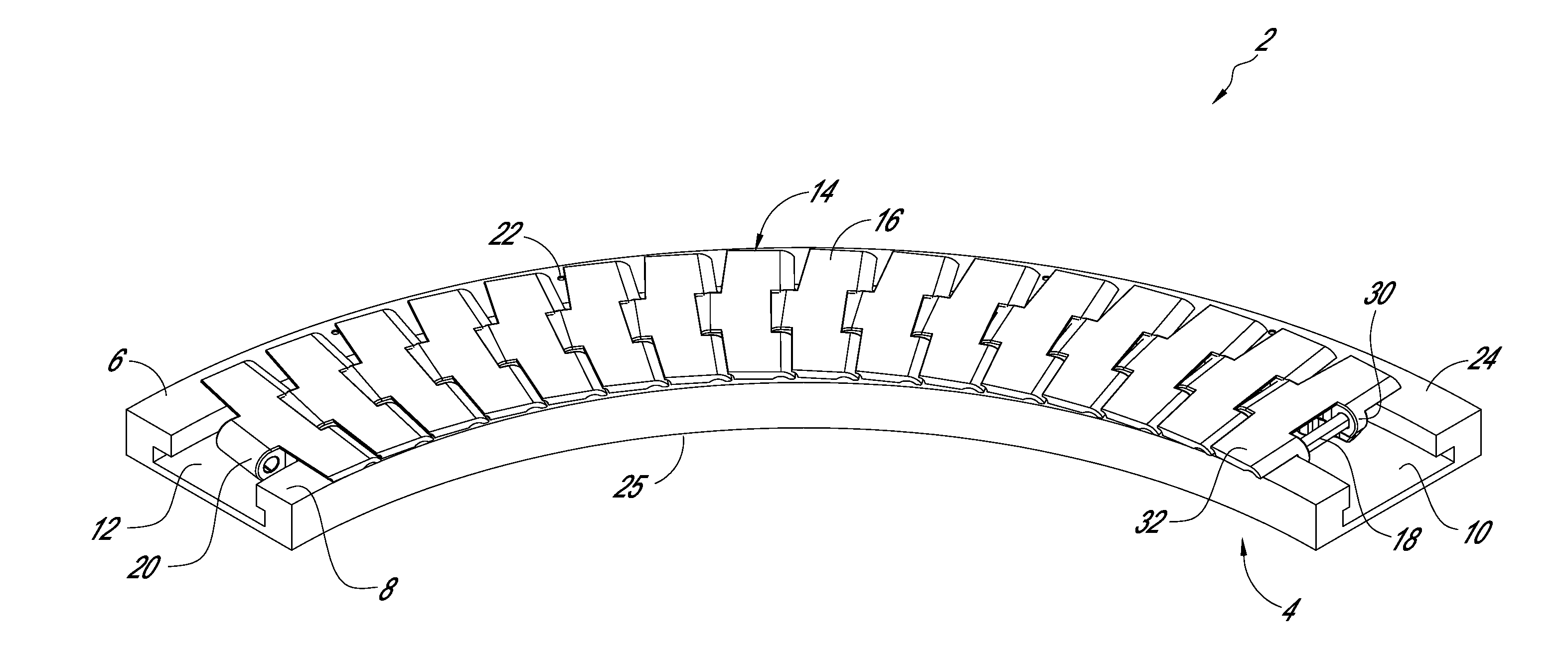
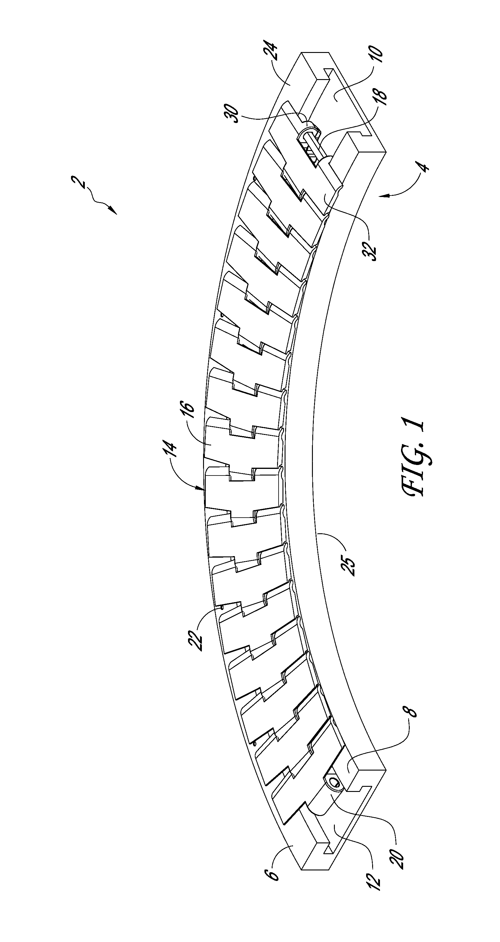
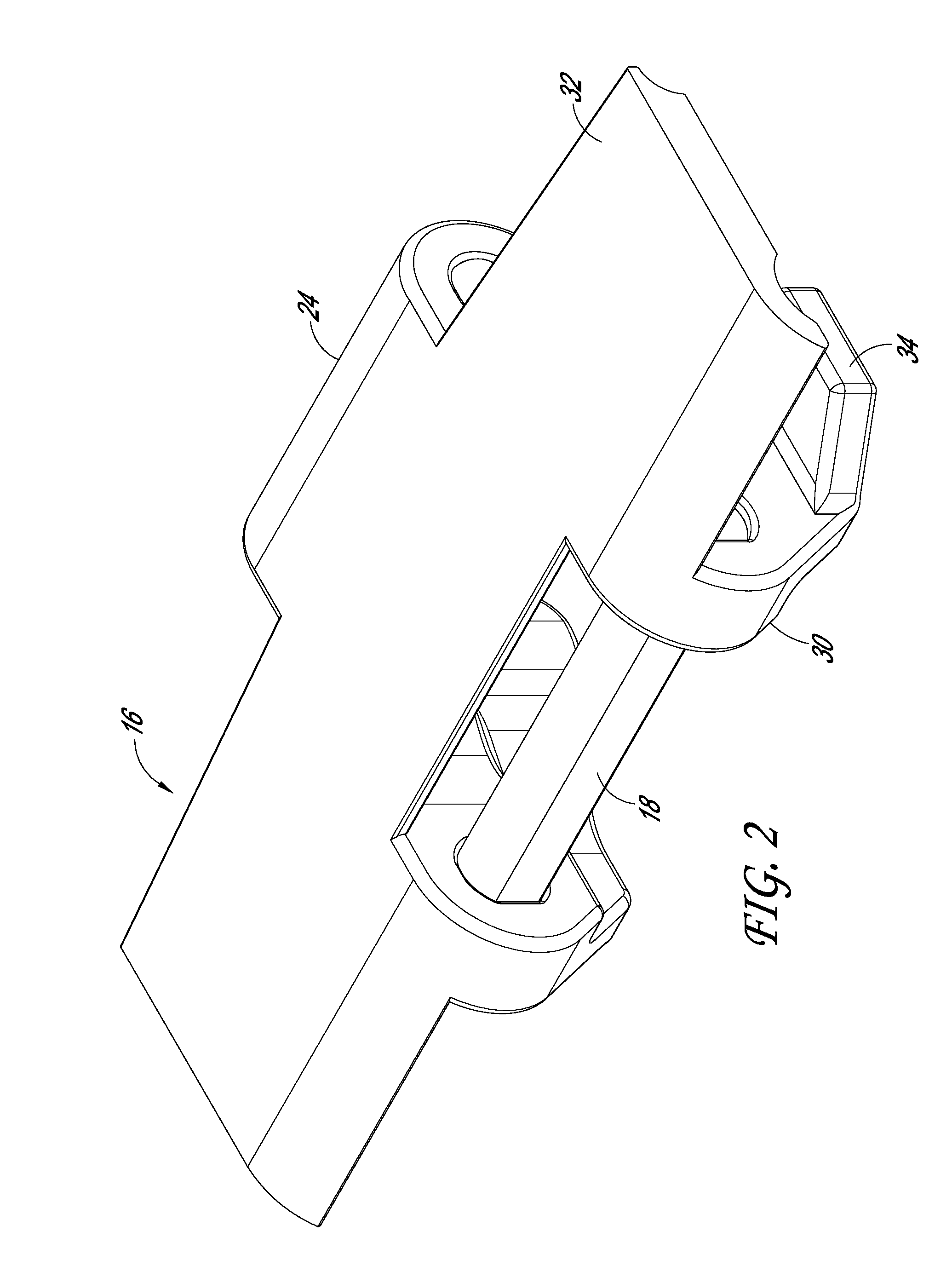
[0035]The conveyor systems described below illustrate various examples that may be employed to achieve one or more desired improvements. These examples are only illustrative and not intended in any way to restrict the general disclosure presented and the various aspects and features of the disclosure. Certain aspects, advantages, and features of the inventions have been described herein. It is not necessary that any or all such aspects, advantages, and features are achieved in accordance with any particular embodiment. Indeed, not all embodiments achieve the advantages described herein, but may achieve different advantages instead. Any structure, feature, or step in one example is contemplated to be used in place of or in addition to any structure, feature, or step of any other example. No features, structure, or step disclosed herein is essential or indispensable.

[0036]Conveyor systems generally include a track and a conveyor movable along (e.g., relative to) the track. Over time, ...


PUM


Abstract

A wear-indicating conveyor track including an upper surface configured to interface with a moveable conveyor and one or more indicators disposed on or in at least the upper surface of the track. The one or more indicators can be configured to be substantially obscured by a conveyor placed on the track upon initial use, and the one or more indicators can be configured to be substantially unobscured by the conveyor when the conveyor is moving relative to the track and the track is in need of repair or replacement.

Description

INCORPORATION BY REFERENCE TO ANY PRIORITY APPLICATIONS[0001]All applications for which a foreign or domestic priority claim is identified in the Application Data Sheet as filed with the present application are hereby incorporated by reference herein under 37 C.F.R. §1.57.[0002]The present application claims priority benefit under 35 U.S.C. §119(e) of U.S. Provisional Application Ser. No. 61 / 718,669, filed Oct. 25, 2012, entitled “WEAR INDICATORS,” the entirety of which is hereby incorporated by reference herein.BACKGROUND[0003]1. Field[0004]The present disclosure relates to devices and methods for indicating the existence and / or the level of wear of components that move relative to each other, and certain embodiments relate to devices and methods for indicating wear in a conveyor system.[0005]2. Description of the Related Art[0006]Certain conveyors are configured to operate along a track. As the conveyor moves along the track, the conveyor contacts portions of the track. The contac...

Claims


Application Information

Patent Timeline
Patent Type & Authority Applications(United States)
IPC IPC(8): B65G41/00
CPCB65G41/00B65G17/086B65G21/22B65G2207/48B65G43/00B65G2812/02069
Inventor MUSICK, SCOTTLAWRENZ, BRIANWAGNER, BRUCE
Owner SOLUS INDAL INNOVATIONS
Learn More