Method of managing an engine failure on a multi-engined aircraft having a hybrid power plant

a hybrid power plant and multi-engine technology, applied in the direction of propellers, rotorcraft, air transport, etc., can solve the problems of degraded performance, difficult operation in the piloting of aircraft, and drawbacks of single-engine aircra

Active Publication Date: 2014-05-01
EUROCOPTER
View PDF1 Cites 63 Cited by
  • Summary
  • Abstract
  • Description
  • Claims
  • Application Information

AI Technical Summary

Benefits of technology

[0042]An object of the present invention is thus to provide a method of managing an engine failure on a rotary wing aircraft having a hybrid power plant that includes at least two fuel-burning engines. Following a failure of at least one engine of the aircraft, the method thus enables the pilot to fly the aircraft safely, i.e. with sufficient driving power and without that stressing each engine that remains operational beyond predetermined operating conditions.

Problems solved by technology

Nevertheless, such single-engined aircraft also present drawbacks.
In the event of damage to the single engine, the power plant and consequently the single-engined aircraft, presents performance that is degraded, possibly to such an extent as to be incapable of driving the main rotor and the tail rotor.
This constitutes a difficult operation in the piloting of aircraft and in particular of single-engined aircraft, and is one of the main reasons for aircraft of this type having a reduced flight envelope and restricted use.
For example, in Europe, a single-engined aircraft is not permitted to overfly a large city.
As a result, flight restrictions such as overflying a large city, do not apply for this type of aircraft.
Nevertheless, the flight capacities authorized for such aircraft can still be limited compared with their maximum capacities in order to ensure some minimum level of safety in flight.
In the event of an engine failing, it is sometimes necessary for a twin-engined aircraft to be able to continue flying on one engine, and thus with reduced performance.
The main consequences of this are an increase in the fuel consumption of the aircraft, which can be made worse by the increase in its empty weight.
In the event of an engine failure on a multi-engined aircraft, a failure of at least one engine leads to power from that engine being lost in part or in full.
In such an aircraft, the probability of having a failure simultaneously on a plurality of engines is relatively low, in compliance with the regulations that are in force.
As a result, such operation needs to be followed by special maintenance with associated costs that can be significant.
Furthermore, the operating durations for the OEI 30″ power rating, for the OEI 2′ power rating, and for the OEI 2′30″ power rating are limited to avoid leading to major, and possibly also immediate, damage to the turboshaft engine or to the power transmission means, such as the main gearbox or “MGB”.
Other solutions have been investigated for delivering such extra power, in particular in order to be able to avoid overdimensioning the engines, but none have yet been applied industrially.
However, one of the major drawbacks of using electric motors is storing the electrical energy needed to operate them.
Several solutions exist for storing this electrical energy, such as batteries, thermal batteries, or supercapacitors, but each of them has its own constraints.
For example, batteries are heavy or indeed very heavy if a large quantity of electrical energy is to be stored, whereas supercapacitors are capable of delivering a high level of electrical power, but only during a very limited length of time.
Furthermore, thermal batteries are for single use only and the length of time they operate after being activated is limited.
Whatever the means used for storing electrical energy, the quantity of electrical energy that is available remains limited, while the weight of the electrical energy storage means can be considerable.
Thus, any improvement in performance that it might be possible to obtain by using one or more electric motors within the power plant of an aircraft suffers from various limitations associated with storing electrical energy.

Method used


Image

  • Method of managing an engine failure on a multi-engined aircraft having a hybrid power plant
  • Method of managing an engine failure on a multi-engined aircraft having a hybrid power plant

Examples


Embodiment Construction

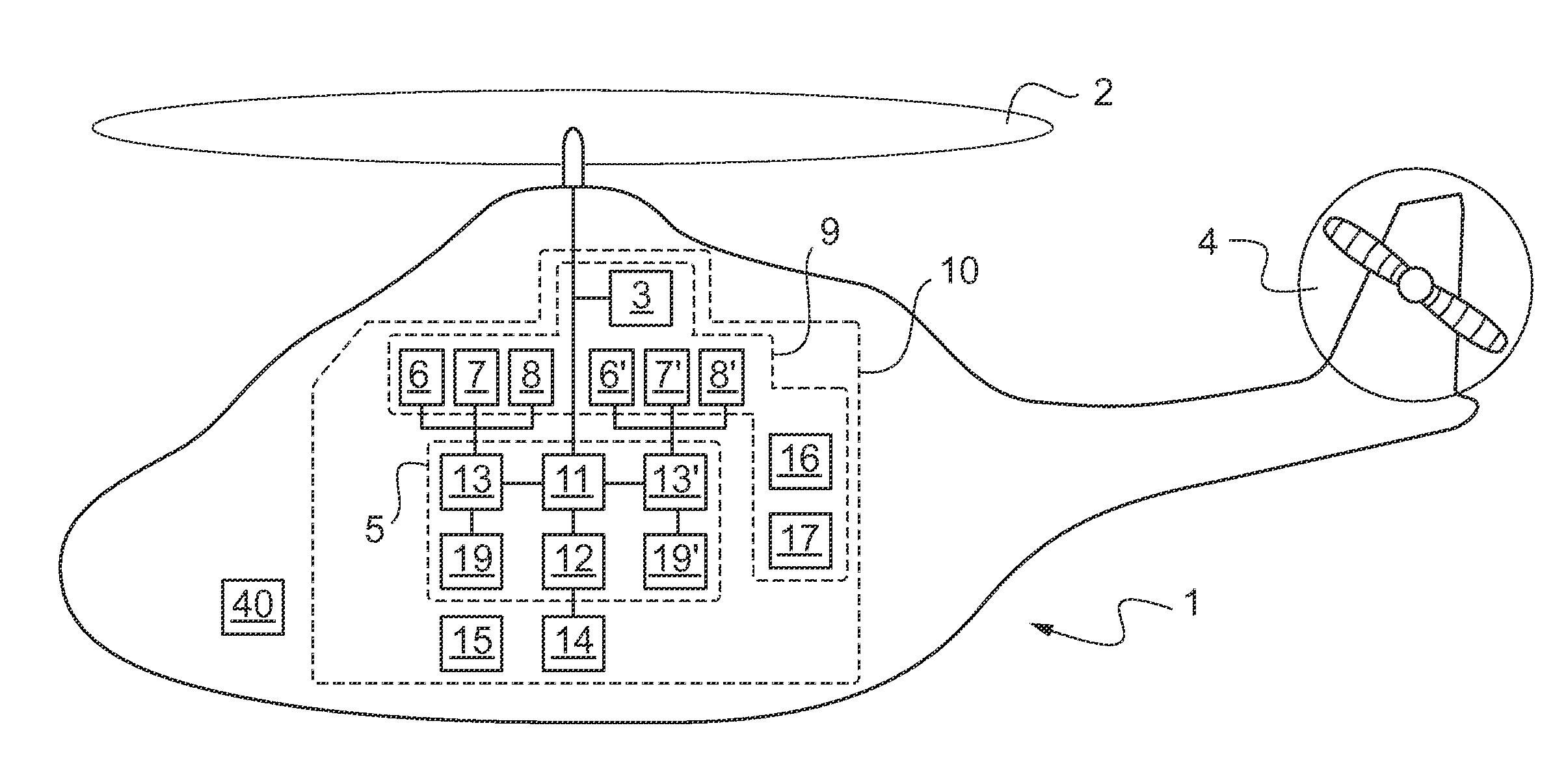
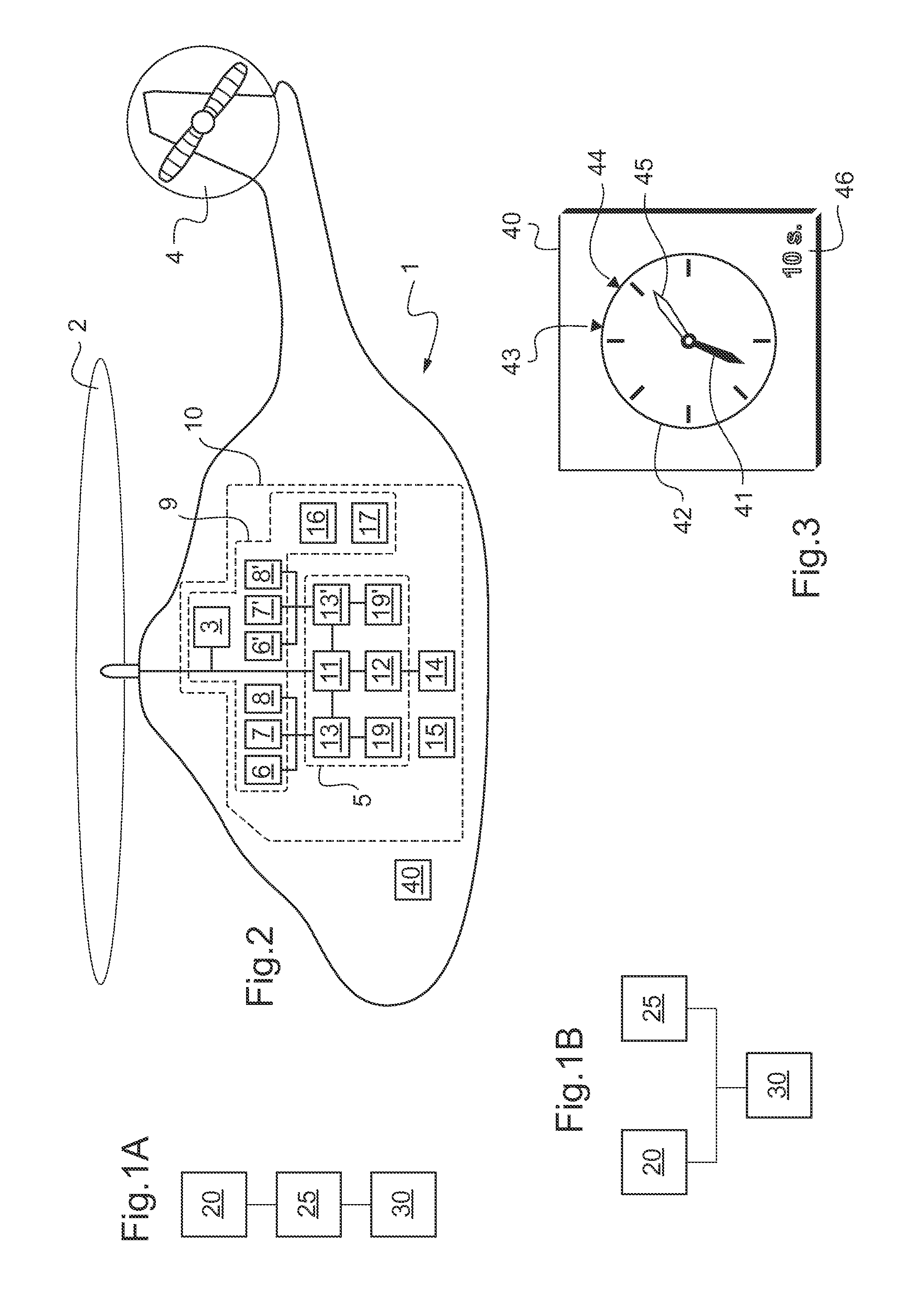
[0134]FIGS. 1A and 1B describe two ways in which the method of the invention for managing an engine failure on a rotary wing aircraft 1 can be conducted. FIG. 2 shows a rotary wing aircraft 1 having a device 10 of the invention for managing engine failure.

[0135]The method and the device 10 thus enable the pilot to fly the aircraft safely, i.e. with sufficient engine power, in spite of a failure of an engine of the aircraft and without such safe flight causing the engine that remains operational to be stressed beyond predetermined operating conditions.

[0136]A device 10 of the invention, as shown in FIG. 2, comprises a hybrid power plant 5 having two fuel burning engines 13, 13′, an electric machine 12 capable of delivering a maximum power Wmax, a main gearbox “MGB”11, and two electronic control units “EECU”19, 19′, each connected to a respective one of the engines 13, 13′ and providing the operating characteristics of each engine 13, 13′. The device 10 also has electrical energy stor...


PUM


Abstract

A method of managing an engine failure on a rotary wing aircraft (1) having a hybrid power plant (5) with at least two fuel-burning engines (13, 13′), at least one electric machine (12), and a main gearbox (11). Said aircraft (1) also has electrical energy storage means (14) and a main rotor (2) mechanically connected to said hybrid power plant (5). In said method, during each flight, the operation of said engines (13, 13′) is monitored in order to detect a failure of any one of them, and then once a failure of one of said engines (13, 13′) has been detected, said electric machine (12) is controlled, if necessary, to deliver auxiliary power We in order to avoid a deficit appearing in the total power WT of said hybrid power plant (5), thereby enabling the pilot of said aircraft (1) to fly said aircraft (1) safely without degrading said hybrid power plant (5).

Description

CROSS REFERENCE TO RELATED APPLICATIONS[0001]The present application claims priority to French patent Application No. FR 12 / 02897 filed Oct. 29, 2012, the disclosure of which is incorporated in its entirety by reference herein.BACKGROUND OF THE INVENTION[0002](1) Field of the Invention[0003]The present invention lies in the technical field of power plants for rotary wing aircraft. The invention relates to a method of managing an engine failure on a rotary wing aircraft having a hybrid power plant with at least two fuel-burning engines. The invention also relates to a rotary wing aircraft having such a hybrid power plant and including a device for managing an engine failure.[0004](2) Description of Related Art[0005]A rotary wing aircraft is conventionally provided with at least one main rotor for providing it with lift and possibly also propulsion, and generally with a tail rotor in particular for opposing the yaw torque exerted by the main rotor on the fuselage of the aircraft and a...

Claims


Application Information

Patent Timeline
Patent Type & Authority Applications(United States)
IPC IPC(8): B64C19/00
CPCB64C19/00B64C27/14B64D27/24B64D31/00B64D35/02B64D35/08B64D2027/026Y02T50/40Y02T50/60
Inventor DYRLA, NADINECONNAULTE, MATTHIEUCEZARD, JORIS
Owner EUROCOPTER
Why Eureka
Try Eureka