Systems And Methods For Producing Substitute Natural Gas

a technology of synthetic gas and system, applied in the direction of combustible gas catalytic treatment, combustible gas purification/modification, sustainable manufacturing/processing, etc., can solve the problems of high auxiliary power and process water requirements, low grade coal reserves including low rank and high ash coal remain underutilized as energy sources, and process efficiency is inefficient and unreliabl

Active Publication Date: 2014-05-01
KELLOGG BROWN & ROOT LLC
View PDF9 Cites 12 Cited by
  • Summary
  • Abstract
  • Description
  • Claims
  • Application Information

AI Technical Summary

Problems solved by technology

Most existing coal gasification processes perform best on high rank (bituminous) coals and petroleum refinery waste products, but these processes are inefficient, unreliable, and expensive to operate when processing low grade coal.
Low grade coal reserves including low rank and high ash coal remain underutilized as ene...

Method used


Image

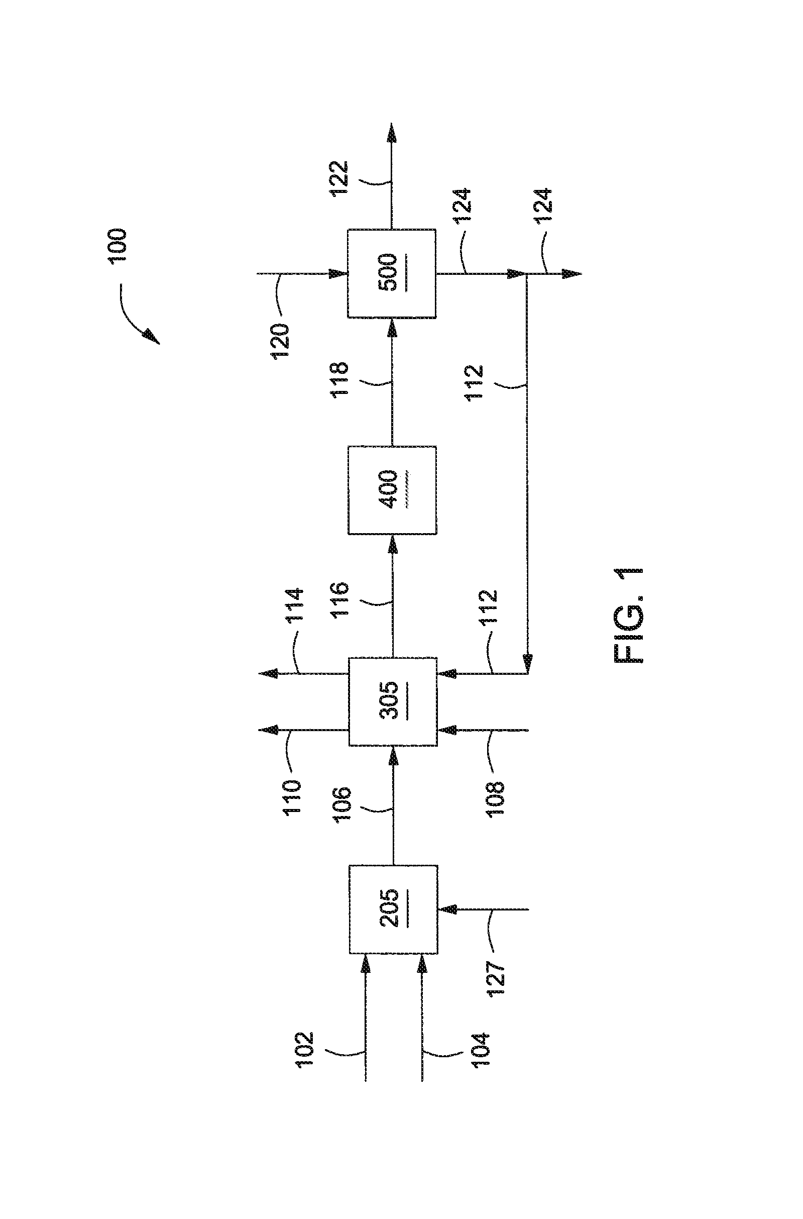
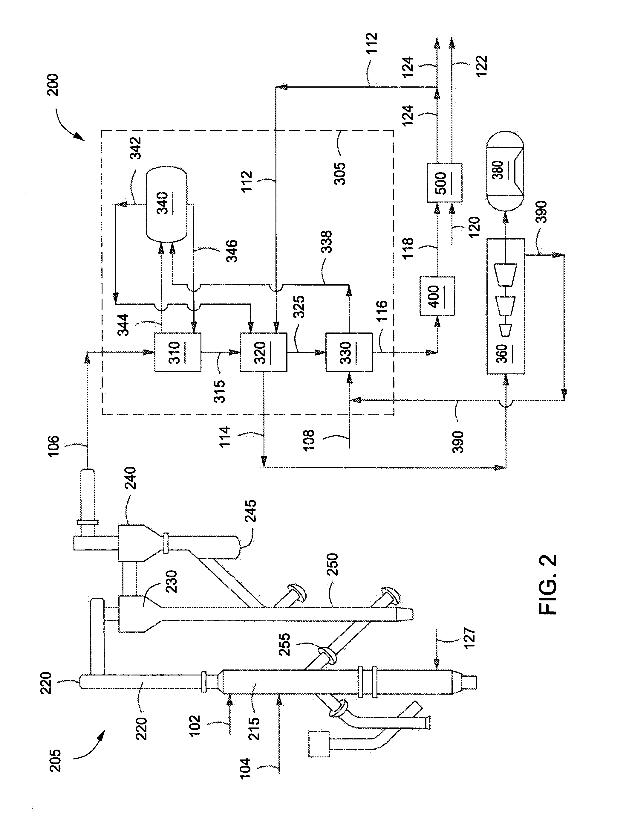
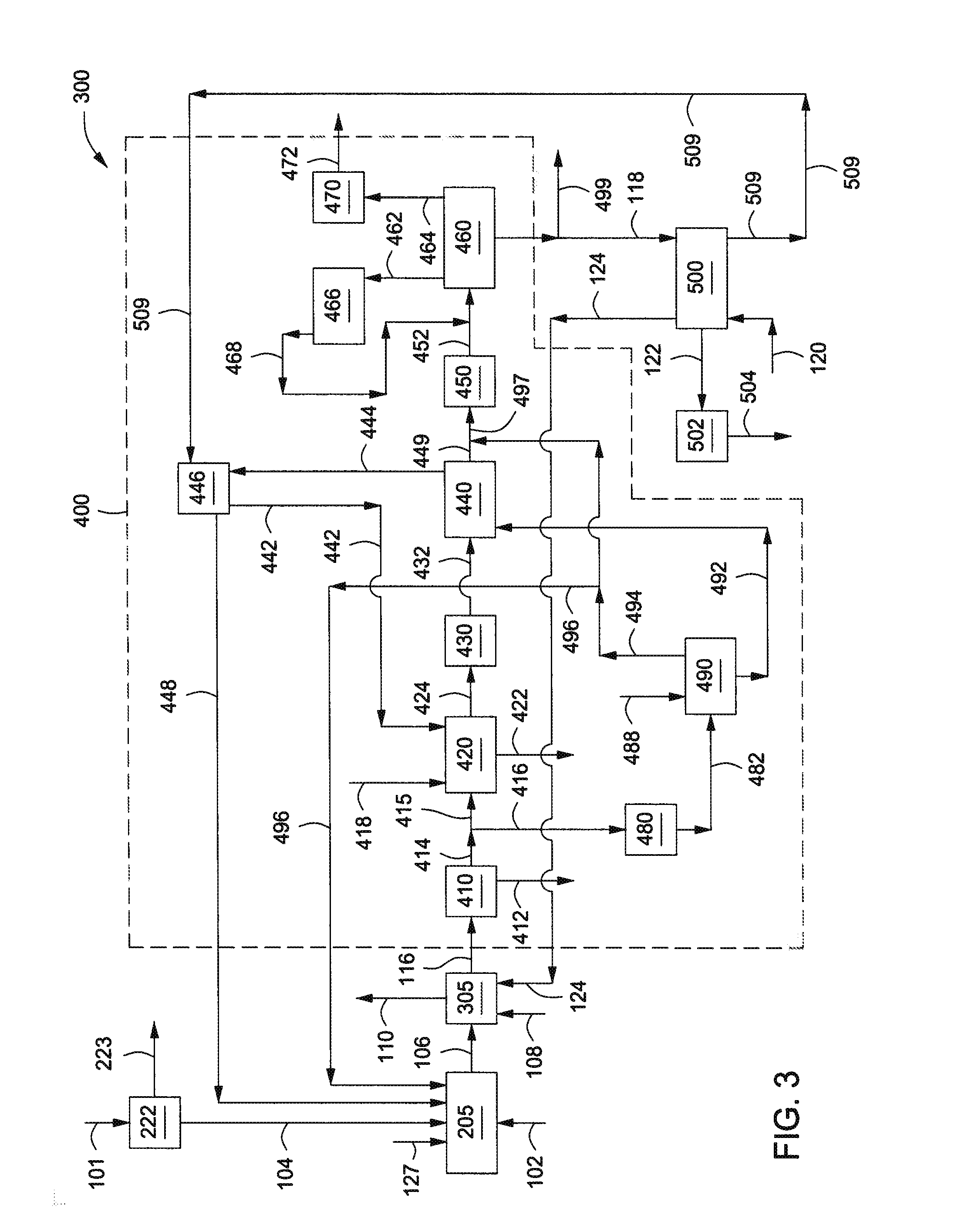
  • Systems And Methods For Producing Substitute Natural Gas
  • Systems And Methods For Producing Substitute Natural Gas
  • Systems And Methods For Producing Substitute Natural Gas

Examples


example i

[0078]One or more of the above described systems can theoretically be used with Wyoming Powder River Basin (“WPRB”) coal. The WPRB coal was given a composition as shown in Table 1 below.

TABLE 1CoalWPRBComponentwt %C51.75O11.52H3.41N0.71S0.26Cl0.01F0.00Moisture27.21Ash5.13HHV, kJ / kg20,385

[0079]The simulated composition of the raw syngas via line 106 from the gasifier 205 was calculated to have a composition as shown in Table 2.

TABLE 2Raw syngas via line 106Temperature927° C.Pressure3600 kPaComponentmol % (wet basis)CO39.7H228.5CO214.3CH44.3NH30.4H2O12.6N20.09Ar0.08H2S750 ppmv HCN250 ppmv COS40 ppmvHF18 ppmvHCl30 ppmv

[0080]Based on simulated process conditions, when the syngas provided from the gasification of the WPRB coal is processed in accordance to one or more embodiments discussed and described above, the treated syngas via line 118 introduced to the methanator 500 can have the composition shown in Table 3.

TABLE 3Treated syngas via line 118Temperature27° C.Pressure2,758 kPaCompo...

example ii

[0083]One or more of the above described systems theoretically can be used with North Dakota Lignite Coal. The North Dakota Lignite Coal was given a composition as shown below in Table 5 below.

TABLE 5CoalNorth Dakota LigniteComponentwt %C44.21O12.45H2.71N0.68S0.60Cl0.01F0.00Moisture29.82Ash9.53HHV, kJ / kg17,058

[0084]The simulated composition of the raw syngas via line 106 from the gasifier 205 was calculated to have a composition as shown in Table 6.

TABLE 6Raw syngas via line 106Temperature899° C.Pressure3,600 kPaComponentmol % (wet basis)CO35.6H225.6CO217.5CH46.1NH30.4H2O14.4N20.09Ar0.07H2S2,007 ppmv  HCN274 ppmvCOS106 ppmvHFNilHCl 15 ppmv

[0085]Based on simulated process conditions, when the raw syngas via line 106 from the gasification of the North Dakota Lignite is processed in accordance to one or more embodiments discussed and described above, the treated syngas via line 118 introduced the methanator 500 can have the composition shown in Table 7.

TABLE 7Treated syngas via line 11...


PUM


Abstract

Systems and methods for producing synthetic gas are provided. The method can include gasifying a carbonaceous feedstock in the presence of an oxidant within a gasifier to provide a raw syngas. The raw syngas can be cooled within a cooler to provide a cooled syngas. The cooled syngas can be processed within a purification system to provide a treated syngas. The purification system can include a saturator adapted to increase a moisture content of the cooled syngas. The treated syngas and a first heat transfer medium can be introduced to a methanator to provide a synthetic gas, a second heat transfer medium, and a methanation condensate. At least a portion of the methanation condensate can be recycled from the methanator to the saturator.

Description

CROSS-REFERENCE TO RELATED APPLICATIONS[0001]This application is a continuation-in-part of U.S. patent application having Ser. No. 13 / 091,980, filed on Apr. 21, 2011, and published as U.S. Publication No. 2012 / 0101323, which is a continuation of U.S. patent application having Ser. No. 12 / 437,999, filed on May 8, 2009, and issued as U.S. Pat. No. 7,955,403, which claims priority to U.S. Provisional Patent Application having Ser. No. 61 / 081,304, filed on Jul. 16, 2008, all of which are incorporated by reference herein.BACKGROUND[0002]1. Field[0003]Embodiments described herein generally relate to systems and methods for producing synthetic gas. More particularly, such embodiments relate to systems and methods for producing synthetic gas using low grade coal or other carbonaceous feedstocks.[0004]2. Description of the Related Art[0005]Clean coal technology using gasification is a promising alternative to meet the global energy demand. Most existing coal gasification processes perform be...

Claims


Application Information

Patent Timeline
IPC IPC(8): C01B3/02B01J7/00
CPCC01B3/16C01B2203/0294C01B2203/0415C01B2203/0445C01B2203/0465C01B2203/0475C01B2203/0485C01B2203/0894C01B2203/86C10J3/56C10K1/004C10K1/005C10K1/024C10K1/101C10K3/04C10J2300/093C10J2300/1662C10J2300/1675C10J2300/1678C10J2300/1884C10J2300/1892C10K1/007Y02P30/00C01B2203/0233C01B3/02B01J7/00
Inventor ARIYAPADI, SIVASHIRES, PHILIP
Owner KELLOGG BROWN & ROOT LLC
Why Eureka
Try Eureka