
Robotic device and method of controlling robotic device

a robotic device and robotic device technology, applied in the direction of electric programme control, program control, instruments, etc., can solve the problems of increasing the generation of vibration, failure to perform accurate failure determination, and deformation of the rigidity of the arm, so as to achieve reliable failure determination

Active Publication Date: 2014-05-01
SEIKO EPSON CORP
View PDF7 Cites 13 Cited by
  • Summary
  • Abstract
  • Description
  • Claims
  • Application Information

AI Technical Summary

Benefits of technology

This patent application describes a way to detect failures in servo motors used in robotic devices. Instead of using a constant threshold value, the application measures the operation data of the actuator and rewrites it based on the sequential information in operation. This allows for the detection of failures in the inertial sensor, which can stop the operation of the robotic device to ensure safe operation. The technical effect is the increased safety of robotic devices.

Problems solved by technology

However, the reduction in weight of the arm results in degradation in the rigidity of the arm, and increases the generation of the vibration due to the deflection of the arm occurring when the arm stops.
However, in these related art documents, when the inertial sensor itself such as the acceleration sensor or the angular velocity sensor used as the standard of the arm control is at fault, even if the data signal obtained is faulty, the control based on the faulty signal is performed, which results in occurrence of danger due to runaway or the like of the robotic device.
However, according to the technology disclosed in the documents mentioned above, since the threshold value is previously set based on the detection value obtained when the sensor to be used operates normally, the detected value might fail to exceed the threshold value in a variety of actual operation states of the robotic device even if the sensor is at fault, which might fail to perform the accurate failure determination.

Method used


Image

  • Robotic device and method of controlling robotic device
  • Robotic device and method of controlling robotic device
  • Robotic device and method of controlling robotic device

Examples


first embodiment

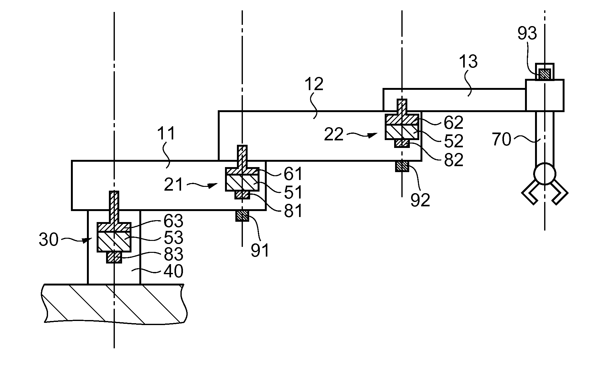
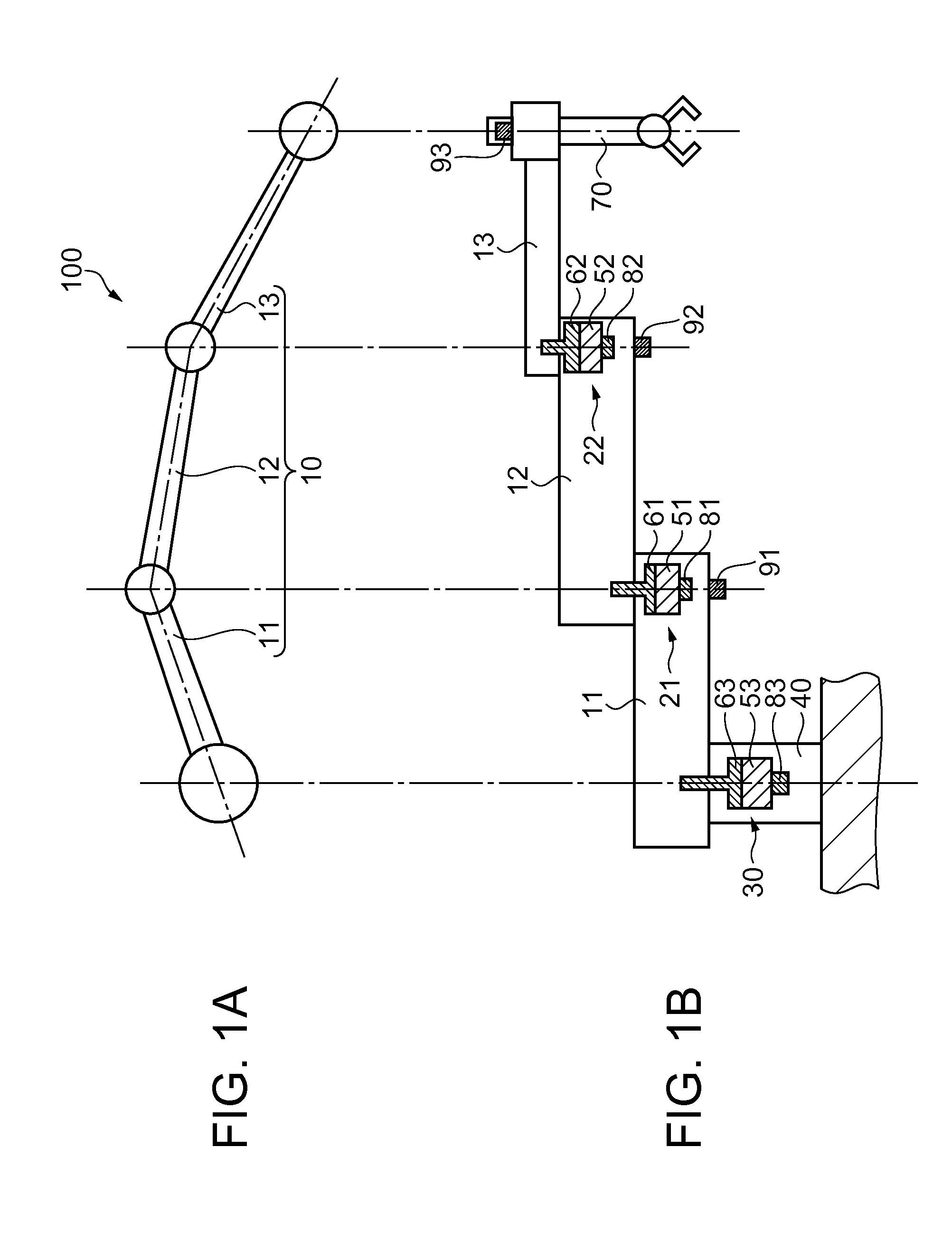
[0041]The first embodiment according to the invention will be explained. FIGS. 1A and 1B are diagrams showing a robotic device according to the first embodiment, wherein FIG. 1A shows a schematic plan view, and FIG. 1B shows a schematic cross-sectional view. The robotic device according to the present embodiment is a so-called three-axis horizontal articulated robot 100 (hereinafter referred to as a robotic device 100) having three arms linked rotatably in a horizontal direction.

[0042]The robotic device 100 is provided with an arm body 10 configured by rotatably and serially linking a first arm 11 and a second arm 12 with a first arm linkage device 21, and the second arm 12 and a third arm 13 with a second arm linkage device 22. The arm body 10 is further linked rotatably to a base body 40, which is fixed to a substrate, with a base body linkage device 30, and thus the robotic device 100 is constituted.

[0043]The first arm linkage device 21 includes an actuator 51, and a torque trans...

second embodiment

[0076]The second embodiment is different from the first embodiment only in the layout of the inertial sensors and the detection data to be the determination standard. Therefore, the explanation will be presented while providing the same constituents as those of the first embodiment with the same reference symbols.

[0077]FIGS. 4A and 4B are diagrams showing a robotic device according to the second embodiment, wherein FIG. 4A shows a schematic plan view, and FIG. 4B shows a schematic cross-sectional view. The robotic device according to the present embodiment is a so-called three-axis horizontal articulated robot 200 (hereinafter referred to as a robotic device 200) having three arms linked rotatably in a horizontal direction.

[0078]The robotic device 200 according to the second embodiment is different from the robotic device 100 according to the first embodiment in the point that two inertial sensors are provided to each of the arms. The first arm 11 is provided with inertial sensors 9...

third embodiment

[0104]Although in the first embodiment and the second embodiment the explanation is presented using the so-called horizontal articulated robotic device, the failure determination of a sensor in a direct acting robotic device will be explained in the third embodiment.

[0105]FIG. 8 is a schematic plan view of a robotic device 1000 according to the third embodiment. Further, FIG. 9 is a schematic diagram of an exterior appearance viewed from the direction of the arrow P in FIG. 8. In order for making the configuration of the robotic device 1000 clear, illustration of, for example, a housing for covering the principal part is omitted from FIG. 8. The robotic device 1000 is provided with a base body 300 fixed to, for example, a work table or a floor, an arm 400 movably attached to the base body 300, and a work holding device 500 attached movably to the arm 400 and having a work holding section 520 for holding a working tool or a work object.

[0106]The base body 300 is provided with a base ...


PUM


Abstract

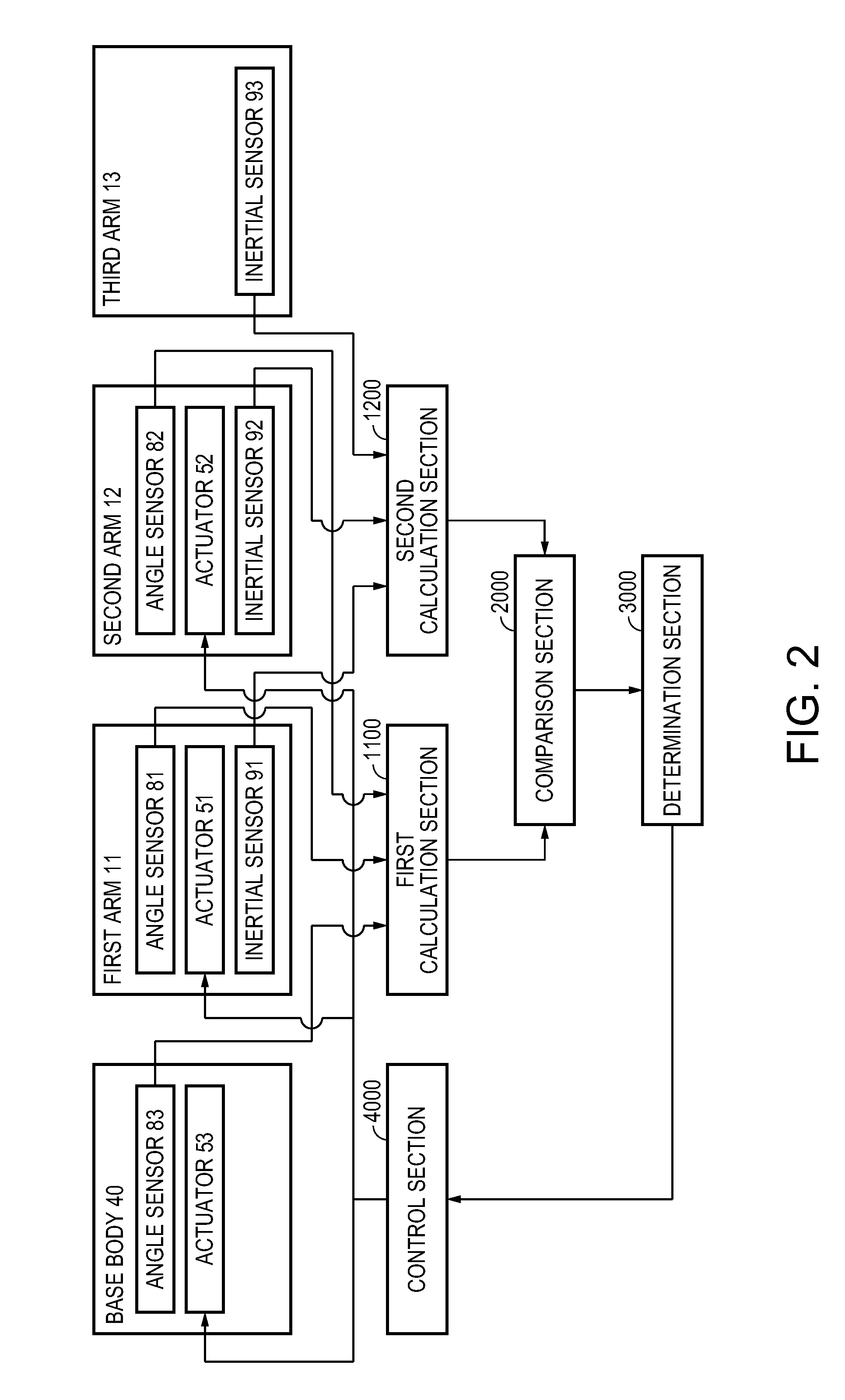
A robotic device having an arm including an actuator and inertial sensor, a first calculator adapted to calculate an angular velocity and an angular acceleration of the actuator based on a rotational angle data from an angle sensor, a second calculator adapted to calculate one of an angular velocity and an angular acceleration of the arm based on an output detected by the inertial sensor, and a comparator adapted to compare one of the angular velocity and the angular acceleration calculated by the first calculator and one of the angular velocity and the angular acceleration calculated by the second calculator with each other, and it is determined that the inertial sensor is at fault if an absolute value of the difference between the actuator and the arm in one of the angular velocity and the angular acceleration in the comparison section is larger than a threshold value.

Description

CROSS-REFERENCE TO RELATED APPLICATIONS[0001]This is a continuation application of U.S. application Ser. No. 13 / 179,894 filed Jul. 11, 2011 which claims priority to Japanese Patent Application No. 2010-157633, filed Jul. 12, 2010 all of which are expressly incorporated by reference herein in their entireties.BACKGROUND[0002]1. Technical Field[0003]The present invention relates to a robotic device, and a method of controlling a robotic device.[0004]2. Related Art[0005]A robotic device having a multijoint structure often used as a part of an IC handler or an assembling device has been in heavy usage in a variety of workplaces. Therefore, how fast and accurately the robotic device can move the arm to a desired position has been a performance specification and a quality of increasing significance for the robotic device.[0006]In general, in order for moving the arm of the robotic device fast and accurately, it is preferable to reduce the inertial force acting on the arm to thereby preven...

Claims


Application Information

Patent Timeline
Patent Type & Authority Applications(United States)
IPC IPC(8): B25J9/16
CPCB25J9/1633B25J9/1674B25J13/088G01C25/005G05B9/03G05B2219/40228
Inventor SASAI, SHIGENORI
Owner SEIKO EPSON CORP
Learn More