Work machine

a work machine and work technology, applied in adaptive control, building repairs, instruments, etc., can solve problems such as the loss of balance of the work machine, and achieve the effect of preventing tipping and stabilizing the work machin

Active Publication Date: 2014-05-01
NIHON KENKI CO LTD
View PDF10 Cites 59 Cited by
  • Summary
  • Abstract
  • Description
  • Claims
  • Application Information

AI Technical Summary

Benefits of technology

[0023]According to the invention, in the case where the control lever of the work machine in the operating state is instantaneously brought back to the stop command position, the control device provided in the work machine predicts a change in stability until each operated movable portion in the work machine completely stops, and calculates a motion limit needed to keep the work machine stable at any time instant until the movable portion in the work machine completely stops, and command information to the actuator driving the movable portion is corrected based on a result of the calculation. Thus, the stability of the work machine in an environment where inertia acts on the work machine can be evaluated accurately while the work machine can be prevented from tipping due to the sudden stop of the upperstructure, the travel base or the front member. In addition, the prediction of the change in the stability and the calculation of the motion limit can be performed by a simple arithmetic operation. Thus, processing for stabilizing the work machine can be performed in real time.

Problems solved by technology

For this reason, the work machine may lose its balance when an excessive work load is applied to the work machine or when the work machine performs an improper operation such as a quick motion in a state in which an overload is applied to the work machine and the front is stretched.

Method used


Image

  • Work machine
  • Work machine
  • Work machine

Examples


Embodiment Construction

[0033]An embodiment of a work machine according to the invention will be described below in accordance with its each item with reference to the drawings.

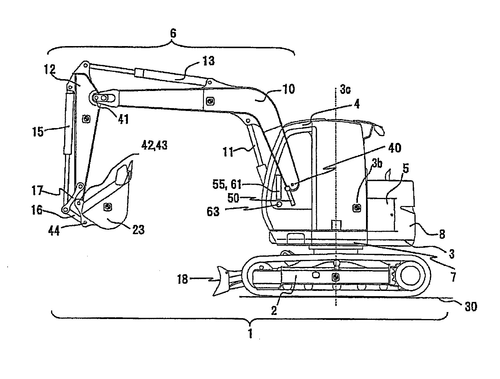
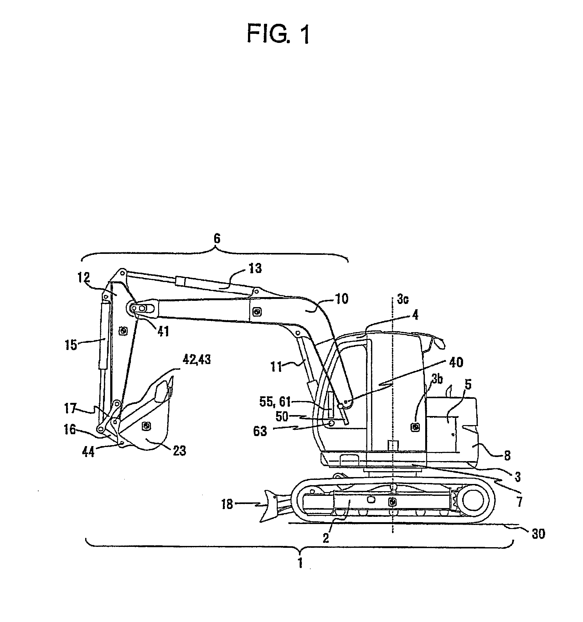
[0034]As shown in FIG. 1, a work machine 1 according to the embodiment is provided with an travel base 2, an upperstructure 3 which is attached to an upper portion of the travel base 2 swingably, and a working front 6 including a multi-joint link mechanism whose one end is connected to the upperstructure 3. The upperstructure 3 is driven to swing around a center shaft 3c by a swing motor 7. An operator's cab 4 and a counterweight 8 are disposed on the upperstructure 3. An engine 5 forming a power system and an operation control device for controlling start / stop and overall motion of the work machine 1 are provided in a necessary portion on the upperstructure 3. Incidentally, the reference numeral 30 in the drawings designates a ground surface.

[0035]The work front 6 has a boom 10 whose one end is connected to the upperstructure 3, an...


PUM


Abstract

To provide a work machine with high stability in which a dynamic balance can be evaluated easily while the influence of a sudden stop of an travel base, an upperstructure and a work front is taken into consideration.A stabilization control calculation unit (60a) and a command value generating unit (60i) are provided in a control device (60) of the work machine. The stabilization control calculation unit (60a) uses a sudden stop model and position information of each movable portion of the travel base and a machine body including the work front (6) to predict a change of stability until reaching a complete stop when a control lever (50) in an operating state is instantaneously brought back to a stop command position, and calculates a motion limit needed to prevent destabilization from occurring at any time instant until reaching the stop. The command value generating unit (60i) corrects the command information to a drive actuator on the basis of the calculation result of the stabilization control calculation unit (60a).

Description

TECHNICAL FIELD[0001]The present invention relates to a work machine used for structure demolition works, waste disposal, scrap handling, road works, construction works, civil engineering works, etc.BACKGROUND ART[0002]As a work machine used for structure demolition works, waste disposal, scrap handling, road works, construction works, civil engineering works, etc., there has been known a work machine in which an upperstructure is attached swingably to an upper portion of an travel base travelling by a power system while a multi-joint work front is attached to the upperstructure swingably in an up / down direction and front members constituting the work front are driven by actuators respectively. As an example of such a work machine, there has been a demolition work machine which is based on a hydraulic excavator. The demolition work machine includes a boom one end of which is connected to an upperstructure, an arm one end of which is connected to a distal end of the boom swingably, a...

Claims


Application Information

Patent Timeline
Patent Type & Authority Applications(United States)
IPC IPC(8): G05B15/02
CPCG05B15/02E02F9/265E02F9/20E02F9/24E04G23/08B60P1/045B60Y2200/412G05B13/047G05B13/048G05B17/02G06F30/15G06F30/17G06F30/23
Inventor MIZUOCHI, MARIKOISHII, AKINORIYAMAGUCHI, JINICHI
Owner NIHON KENKI CO LTD
Why Eureka
Try Eureka