X-ray detection device and method of driving an x-ray detection panel

a detection device and detection panel technology, applied in the field of xray detection techniques, can solve the problems of high cost, noise due to line capacitance increase, fill-factor reduction, etc., and achieve the effect of reducing frame rate, reducing image lag, and reducing image lag

Active Publication Date: 2014-05-08
SAMSUNG DISPLAY CO LTD
View PDF2 Cites 4 Cited by
  • Summary
  • Abstract
  • Description
  • Claims
  • Application Information

AI Technical Summary

Benefits of technology

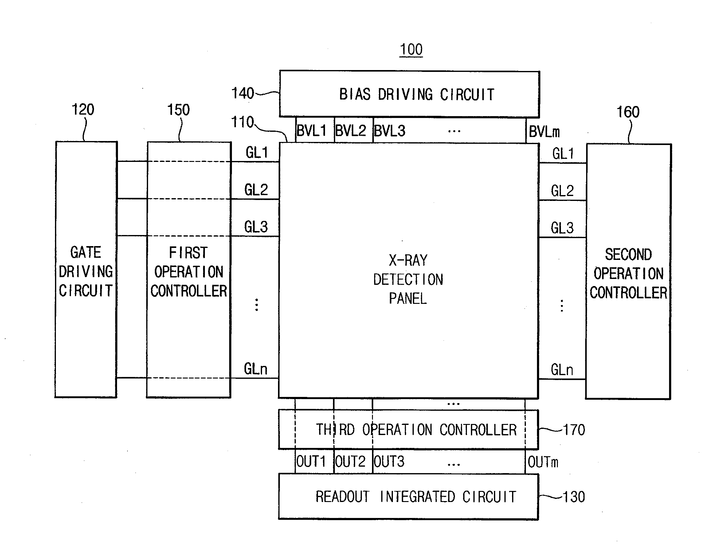
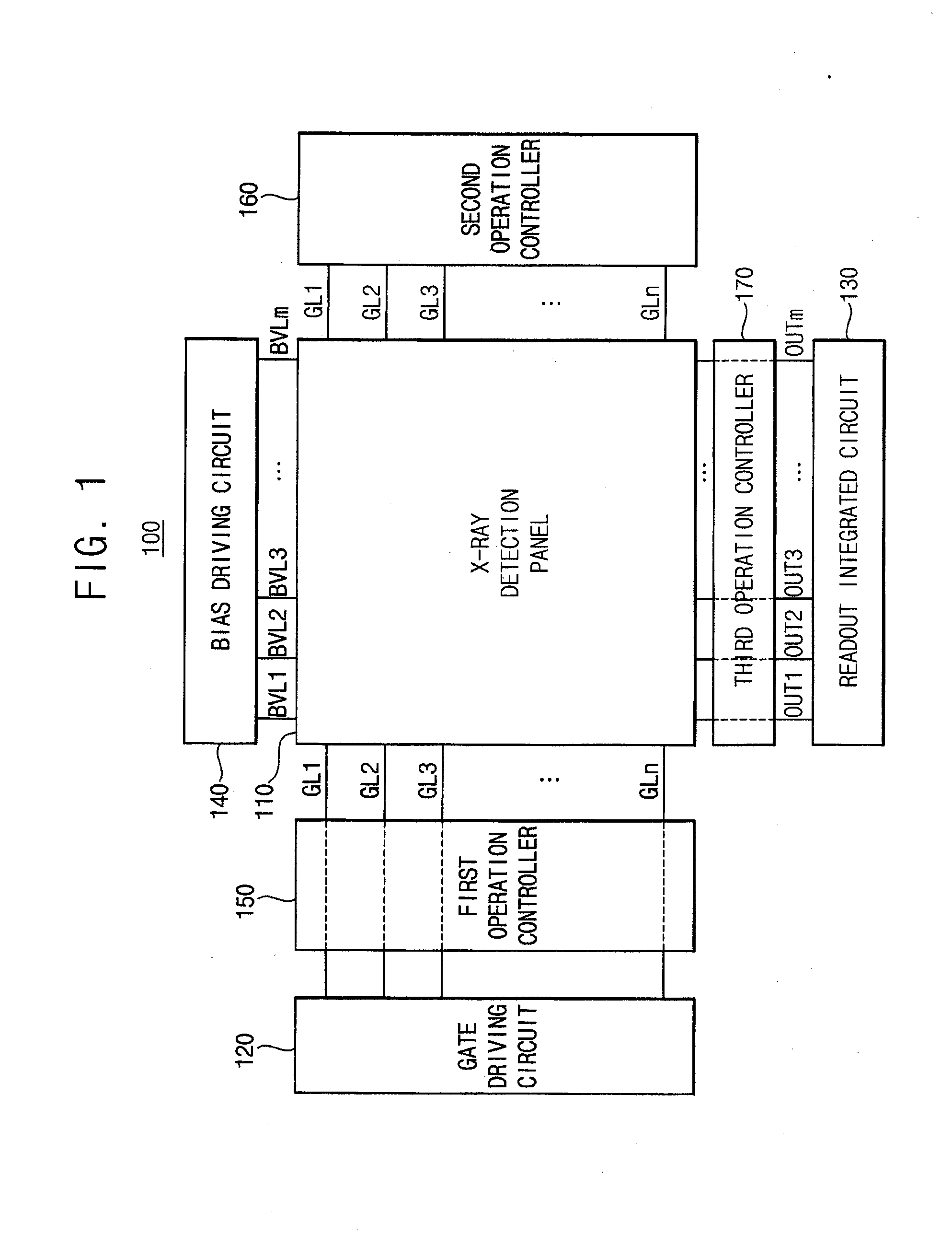
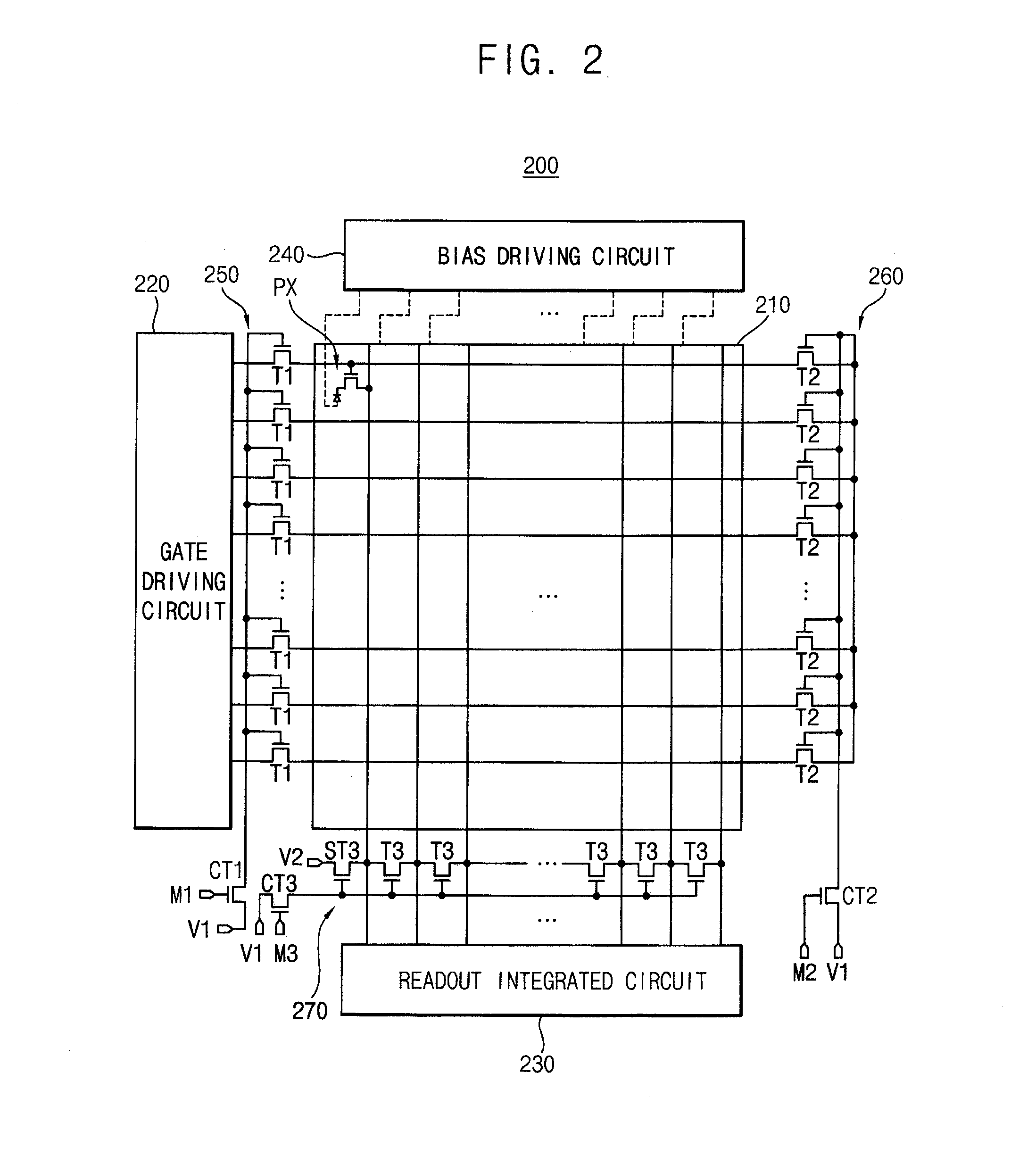
[0034]Therefore, an X-ray detection device according to example embodiments efficiently reduces an image-lag without fill-factor decreases and frame-rate decreases by simultaneously performing a forward-biasing operation on all pixel circuits included in an X-ray detection panel, and by simultaneously performing an initializing operation on all pixel circuits included in the X-ray detection panel.
[0035]In addition, a method of driving an X-ray detection panel according to example embodiments efficiently reduces an image-lag without fill-factor decreases and frame-rate decreases by simultaneously performing a forward-biasing operation on all pixel circuits included in the X-ray detection panel, and by simultaneously performing an initializing operation on all pixel circuits included in the X-ray detection panel.

Problems solved by technology

In addition, the conventional X-ray detection devices may result in high costs because a new chemical film is required to detect the X-ray exposure.
However, compared to when each pixel circuit includes the switching transistor, a fill-factor may decrease, and a noise due to line capacitance increases may occur in the flat panel type X-ray detection device when each pixel circuit includes the switching transistor and the additional transistors.
In addition, a frame-rate may necessarily decrease in the flat panel type X-ray detection device when each pixel circuit alternately performs the X-ray detecting operation and the forward-biasing operation for each gate-line.
Therefore, these approaches may not be appropriate for manufacturing the flat panel type X-ray detection device in a big size.

Method used


Image

  • X-ray detection device and method of driving an x-ray detection panel
  • X-ray detection device and method of driving an x-ray detection panel
  • X-ray detection device and method of driving an x-ray detection panel

Examples


Embodiment Construction

[0047]Various example embodiments will be described more fully hereinafter with reference to the accompanying drawings, in which some example embodiments are shown. The present inventive concept may, however, be embodied in many different forms and should not be construed as limited to the example embodiments set forth herein. Rather, these example embodiments are provided so that this disclosure will be thorough and complete, and will fully convey the scope of the present inventive concept to those skilled in the art. In the drawings, the sizes and relative sizes of layers and regions may be exaggerated for clarity. Like numerals refer to like elements throughout.

[0048]It will be understood that, although the terms first, second, third etc. may be used herein to describe various elements, these elements should not be limited by these terms. These terms are used to distinguish one element from another. Thus, a first element discussed below could be termed a second element without de...


PUM


Abstract

An X-ray detection device includes an X-ray detection panel having a plurality of gate-lines, a plurality of data-lines, a plurality of bias-lines, a plurality of pixel circuits, a gate driving circuit that sequentially provides a gate signal to the pixel circuits via the gate-lines when an X-ray detecting operation is performed, a readout integrated circuit that performs a readout operation of a detection signal that is output from the pixel circuits via the data-lines when the X-ray detecting operation is performed, a bias driving circuit that provides a forward-bias voltage or a reverse-bias voltage to the pixel circuits via the bias-lines, and an operation control circuit that controls a forward-biasing operation and an initializing operation to be simultaneously performed on the pixel circuits.

Description

CROSS-REFERENCE TO RELATED APPLICATION[0001]This application claims priority to and the benefit of Korean Patent Applications No. 10-2012-0123950, filed on Nov. 5, 2012 in the Korean Intellectual Property Office (KIPO), the contents of which are incorporated herein in its entirety by reference.BACKGROUND[0002]1. Technical Field[0003]Example embodiments relate generally to an X-ray detection technique. More particularly, embodiments of the inventive concept relate to an X-ray detection device and a method of driving an X-ray detection panel.[0004]2. Description of the Related Art[0005]Generally, conventional X-ray detection devices detect an X-ray using a chemical film. Thus, the conventional X-ray detection devices can be used only for an unmoving subject. In addition, the conventional X-ray detection devices may result in high costs because a new chemical film is required to detect the X-ray exposure. For this reason, a flat panel type X-ray detection device has been suggested. The...

Claims


Application Information

Patent Timeline
Patent Type & Authority Applications(United States)
IPC IPC(8): G01T1/24
CPCG01T1/24H04N5/32A61B6/00H01L27/14
Inventor SHIN, CHUL-WOOYOON, KYUNG-HUN
Owner SAMSUNG DISPLAY CO LTD
Why Eureka
Try Eureka