Wireless power transfer system for wirelessly transferring electric power in noncontact manner by utilizing resonant magnetic field coupling

a wireless transmission and noncontact technology, applied in the direction of transformers/inductances, basic electric elements, inductances, etc., can solve the problems of difficult control of transmission frequency change during power transmission, no method of reducing electrical stress to the components or elements of the system, etc., to achieve the effect of relieving electrical stress to the components

Active Publication Date: 2014-05-08
PANASONIC INTELLECTUAL PROPERTY MANAGEMENT CO LTD
View PDF3 Cites 23 Cited by
  • Summary
  • Abstract
  • Description
  • Claims
  • Application Information

AI Technical Summary

Benefits of technology

[0015]According to the above configuration, there can be provided the wireless power transfer system capable of relieving electrical stress to the components or elements as compared with the prior art, the wireless power transmitter apparatus for use in the wireless power transfer system, and the frequency controller apparatus and the power transfer method for use in the

Problems solved by technology

However, the Patent Documents 2 and 3 describe no method of reducing the electrical stress to the components or elements of the system during the operation of the wireless power transfer system.
Moreover, it is difficult to control

Method used


Image

  • Wireless power transfer system for wirelessly transferring electric power in noncontact manner by utilizing resonant magnetic field coupling
  • Wireless power transfer system for wirelessly transferring electric power in noncontact manner by utilizing resonant magnetic field coupling
  • Wireless power transfer system for wirelessly transferring electric power in noncontact manner by utilizing resonant magnetic field coupling

Examples


first embodiment

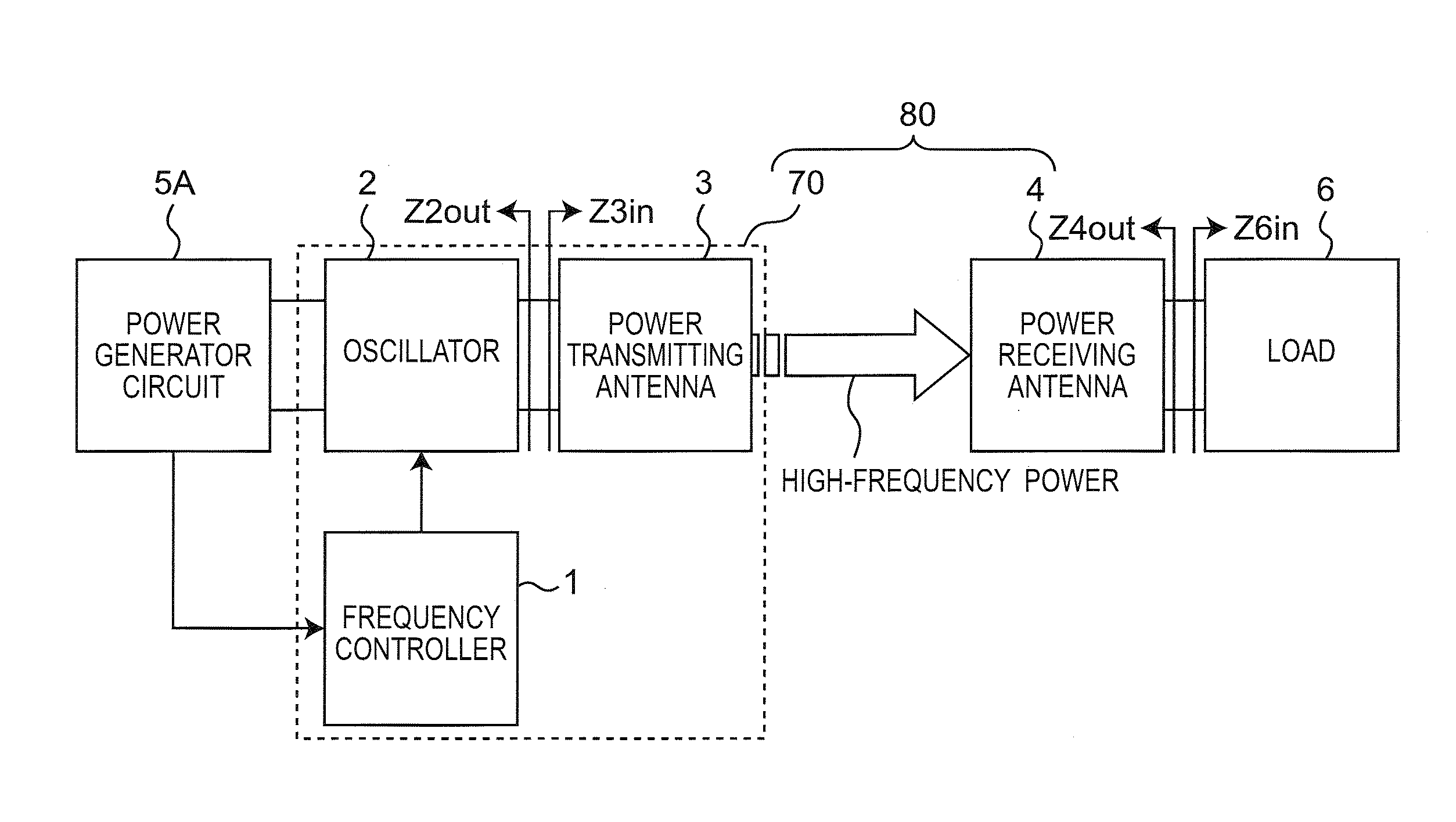
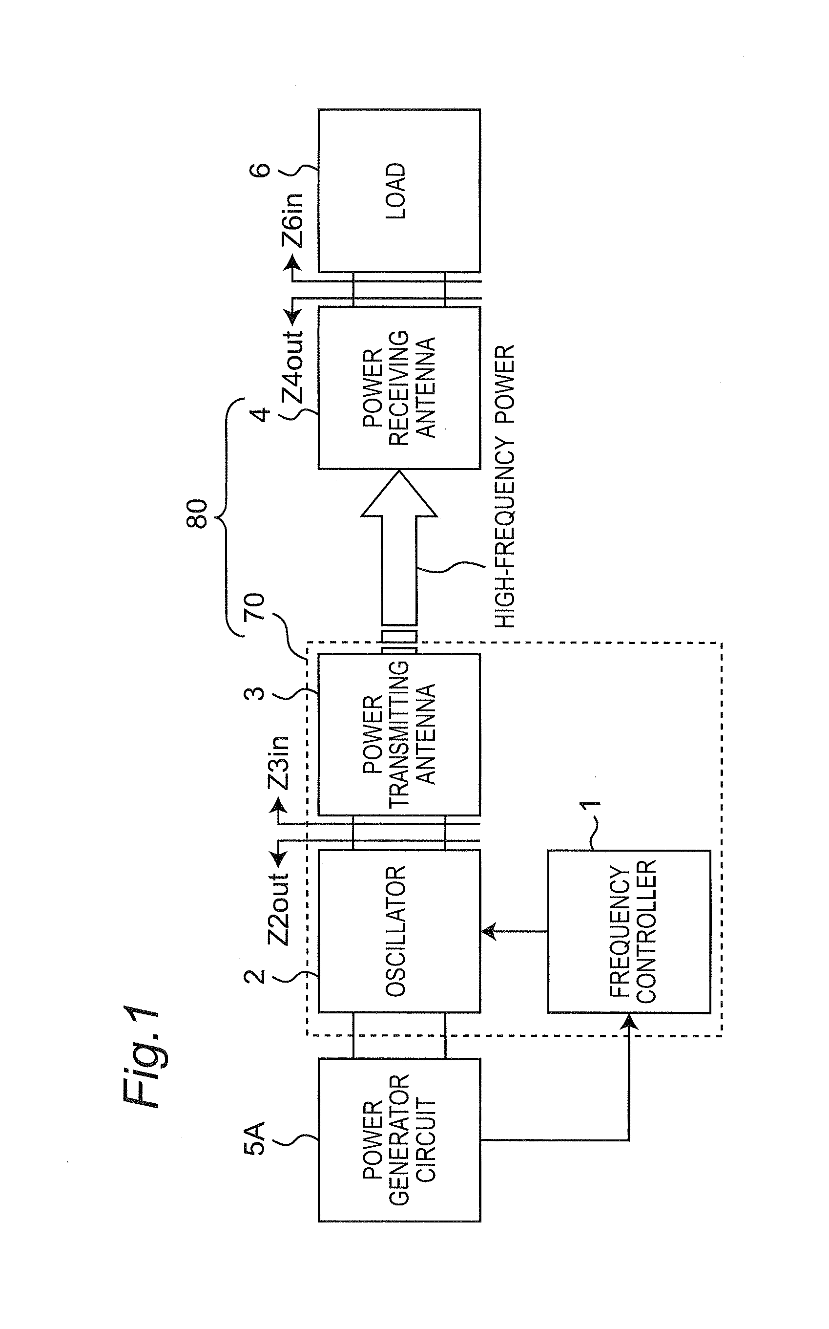
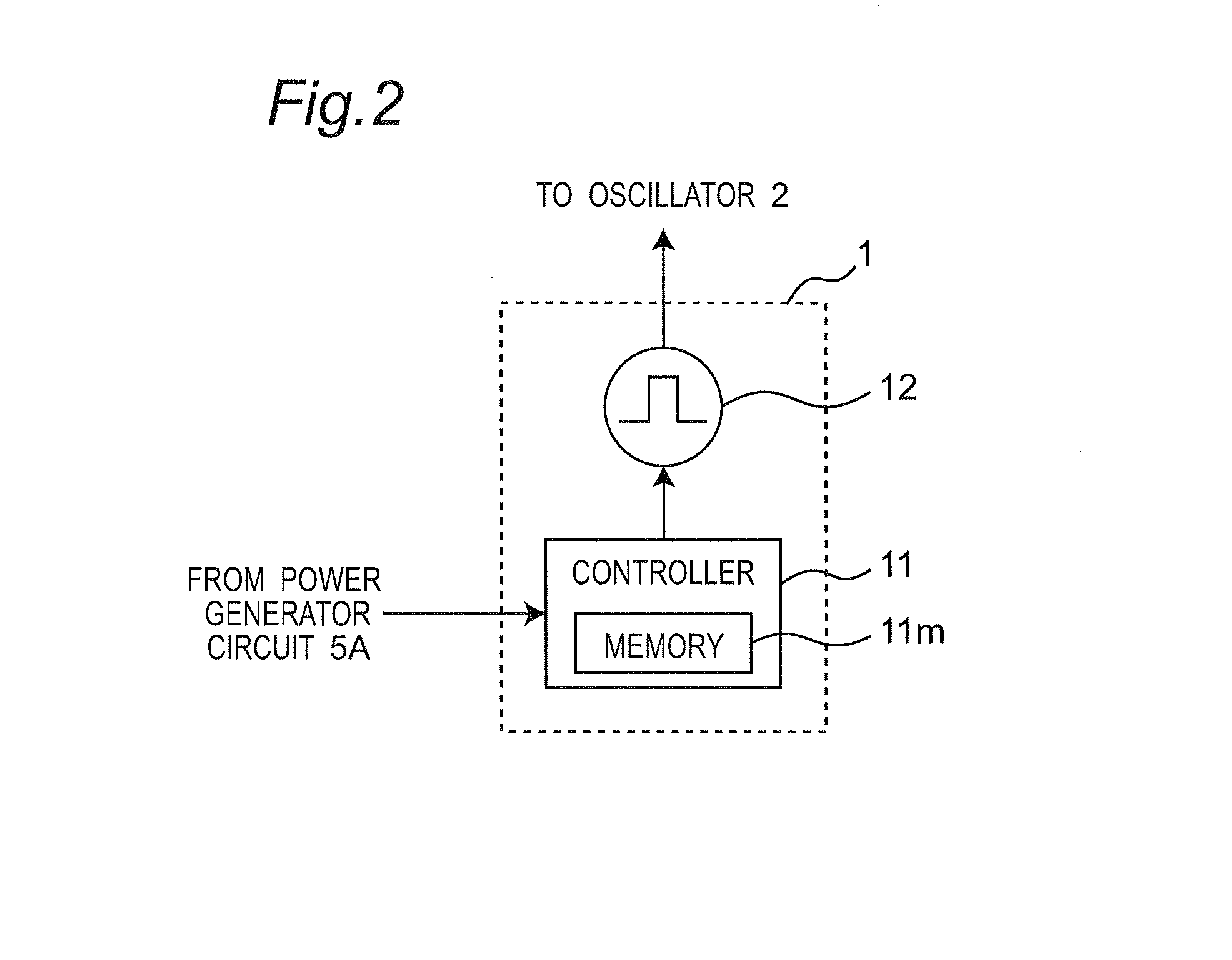
[0035]FIG. 1 is a block diagram showing a configuration of a wireless power transfer system 80 according to a first embodiment of the present disclosure, and FIG. 2 is a block diagram showing a configuration of a frequency controller apparatus 1 of FIG. 1. FIG. 3 is a circuit diagram showing a configuration of a power transmitting antenna 3 of FIG. 1, and FIG. 4 is a circuit diagram showing a configuration of a power receiving antenna 4 of FIG. 1. Further, FIG. 5 is a perspective view showing a configuration of a power transmitting coil Lt and a power receiving coil Lr of FIG. 4.

[0036]Referring to FIG. 1, a power generator circuit 5A including, for example, solar cells outputs generated DC power to the wireless power transfer system 80. Moreover, the wireless power transfer system 80 converts the DC power from the power generator circuit 5A into high-frequency power, and wirelessly transmits the power to a load 6. The configuration and operation of the wireless power transfer system...

first modified embodiment

OF FIRST EMBODIMENT

[0059]FIG. 9 is a block diagram showing a configuration of a wireless power transfer system 80 according to the first modified embodiment of the first embodiment of the present disclosure. Referring to FIG. 9, the power supply circuit 5 converts AC power from a commercial AC power source into DC power, and outputs a resulting power to the wireless power transfer system 80. Moreover, the wireless power transfer system 80 converts the DC power from the power supply circuit 5 into high-frequency power, and transmits a resulting power to the load 6. The magnitude of the power that should be transmitted from the power transmitting antenna 3 to the power receiving antenna 4 changes in accordance with a change in the power necessary for the load 6. In the present modified embodiment, the controller 11 of the frequency controller apparatus 1 of FIG. 9 retrieves the optimum transmission frequency fopt when the voltage and current outputted to the load 6 become the desired ...

second embodiment

[0062]FIG. 11 is a graph showing a method of setting the transmission frequency ftr according to the second embodiment of the present disclosure. Referring to FIG. 11, the controller 11 controls the transmission frequency ftr to first set the transmission frequency ftr to the minimum frequency fL at a timing t3, and start the power transfer. When a predetermined convergence time Δt has elapsed from the timing t1, the controller 11 measures the voltage and current outputted to the load 6. Then, the controller 11 judges whether or not the measured voltage and current are the desired voltage and current. When the measured voltage and current are not any desired voltage and current, the controller 11 increases the transmission frequency ftr by the predetermined increase amount ΔfLH, and the controller 11 measures the voltage and current outputted to the load 6 when the predetermined convergence time Δt has elapsed. Subsequently, the controller 11 measures the voltage and current outputt...


PUM


Abstract

There is provided a frequency controller apparatus for use in a wireless power transmitter apparatus configured to wirelessly transmit an inputted power from a power transmitting antenna that includes a first resonant circuit, toward a power receiving antenna that includes a second resonant circuit and is electromagnetically coupled to the power transmitting antenna at a predetermined transmission frequency. The frequency controller apparatus includes a controller for changing the transmission frequency during a power transfer, and the controller sets a decrease amount when decreasing the transmission frequency, so that the decrease amount is smaller than an increase amount when the transmission frequency is increased.

Description

CROSS-REFERENCE TO RELATION APPLICATION[0001]This is an application which claims priority of U.S. provisional patent application No. 61 / 721,691 filed on Nov. 2, 2012, the contents of which is incorporated herein by reference.BACKGROUND OF THE DISCLOSURE[0002]1. Technical Field[0003]The technical field relates to a wireless power transfer system configured to wirelessly transfer electric power in a noncontact manner by utilizing resonant magnetic field coupling, a wireless power transmitter apparatus for use in the wireless power transfer system, and a frequency controller apparatus and a power transfer method to be used for the wireless power transmitter apparatus.[0004]2. Description of the Related Art[0005]A Patent Document 1 discloses a wireless power transfer apparatus to transmit energy via a space between two resonant circuits. In this wireless power transfer apparatus, vibrational energy is wirelessly transmitted (in a noncontact manner) by coupling of two resonant circuits v...

Claims


Application Information

Patent Timeline
IPC IPC(8): H02J17/00
CPCH02J17/00H02J50/12H02J50/90
Inventor KANNO, HIROSHI
Owner PANASONIC INTELLECTUAL PROPERTY MANAGEMENT CO LTD
Why Eureka
Try Eureka