Electric motor

Active Publication Date: 2014-05-08
ATE ANTRIEBSTECHN & ENTWICKLUNGS
View PDF6 Cites 9 Cited by
  • Summary
  • Abstract
  • Description
  • Claims
  • Application Information

AI Technical Summary

Benefits of technology

[0010]If the projections extend radially inwards, an improved force action of the magnetic fields of the individual coil windings on the rotor results because the coil windings are disposed closer to the rotor.
[0011]If the projections extend radially outwards, the manufacture of the stator is facilitated because the coil windings may be placed onto the projections of the winding support from outside.
[0012]In one embodiment, the winding carrier is made of a stack of stampings. The realization of the winding support with a stack of stampings has the advantage that the complex shape of the winding carrier with the projections can be realized in a simple technical procedure. Moreover, by the use of a stack of stampings, eddy currents in the winding carrier are reduced, in particular if the stampings are mutually insulated. In a particular embodiment, the stampings consist of a nickel steel. Nickel steel on the one hand has a good ferromagnetic (soft-magnetic) characteristic, and on the other hand it is particularly corrosion-resistant. In particular if electric motors are used according to the invention in medical instruments, such as e. g. dental drills, bone cutters, etc., the electric motor must be resistant to c

Problems solved by technology

To ensure the supply with media, it is either necessary to enlarge the diameter of the instrument, making handling more difficult, or the motor must be reduced in size, thus deteriorating the operation behavior and the efficiency of the electric motor.
Furthermore, the inhomogeneities then occurring in the return body by the line passages will have an influence on the stator magnetic field, whereby the operation properties may deteriorate.
However, a disadvantage of this arrangement is that by the more homogenous magnetic field, a sensorless detection of the

Method used


Image

  • Electric motor
  • Electric motor
  • Electric motor

Examples


Example

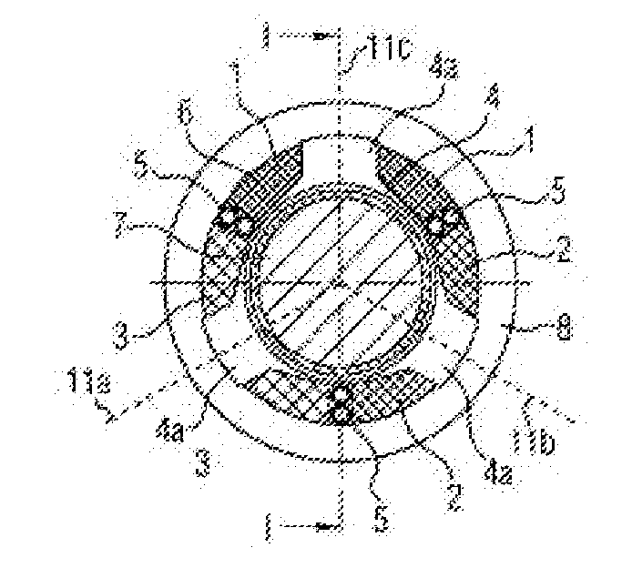
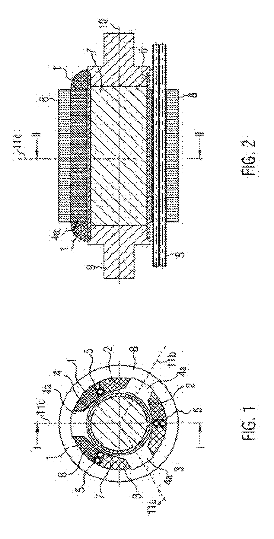
[0022]FIGS. 1 and 2 show cross-sections of an electric motor according to the present invention. FIG. 1 shows a section transverse to the axis of rotation of the rotor, and FIG. 2 shows a cross-section longitudinal to the axis of rotation of the rotor.

[0023]In FIG. 1, reference numerals 1, 2 and 3 designate coil windings, reference numeral 4 designates the winding carrier, reference numeral 4a designates a projection of the winding carrier 4, reference numeral 5 designates media lines, reference numeral 6 designates a hermetic casing of a rotor magnet 7, and reference numeral 8 designates a return body. Reference numerals 11a, 11b and 11c designate axes of the coil windings 1, 2 and 3. The coil windings 1, 2 and 3 surround the projections 4a of the winding carrier 4.

[0024]When current is supplied to the coil windings 1, 2 and 3, a magnetic field is formed in the projections 4a parallel to the coil axes 11a, 11b and 11c, so that a torque can be applied to the rotor magnet 7 rotatably...


PUM


Abstract

The invention relates to an electric motor having a rotatably mounted rotor magnet and a stator enclosing the rotor magnet, said stator comprising at least three coil windings and a winding carrier, wherein coil axes of the at least three coil windings are disposed radially to an axis of rotation of the rotor magnet in various radial directions. The coil windings of the electric motor are designed so that a gap that is parallel to the axis of rotation of the rotor magnet extends between at least two adjacent coil windings, in which at least one media line extending in the longitudinal direction is provided.

Description

FIELD OF THE INVENTION[0001]The invention relates to an electric motor according to the preamble of claim 1.DESCRIPTION OF PRIOR ART[0002]Electric motors of the type mentioned in the beginning are employed, for example, in medical appliances, such as drills, in particular dental drills, cutters, bone cutters, dental mills and saws. In applications of this type, however, various particularities must be observed. Among other things, a compact structure is required, so that the medical instrument comfortably lies in the hand and permits precise and effortless working. At the same time, the motor should be efficient, so that no changes of speed occur under load. It is furthermore necessary for medical instruments to supply the working area with additional media. For example, the working area must be selectively illuminated and cooled or cleaned with water and / or air. These media must be brought to the working area (operation area) through supply lines that are especially provided for th...

Claims


Application Information

Patent Timeline
IPC IPC(8): H02K1/12
CPCH02K1/12A61B17/1628A61B2217/005A61B2217/007A61C1/06H02K3/24H02K3/44H02K7/14H02K21/028A61B2090/306
Inventor THALER, WOLFGANGVOHRER, MARK
Owner ATE ANTRIEBSTECHN & ENTWICKLUNGS
Why Eureka
Try Eureka