Magnetic resonance imaging apparatus and gradient magnetic field waverform estimation method
a magnetic field waverform and magnetic resonance imaging technology, applied in the field of magnetic resonance imaging, can solve the problems of large application strength of gradient magnetic field pulses, excitation positions, and large error in excitation profiles. to achieve the effect of suppressing image distortion or artifacts
- Summary
- Abstract
- Description
- Claims
- Application Information
AI Technical Summary
Benefits of technology
Problems solved by technology
Method used
Image
Examples
first embodiment
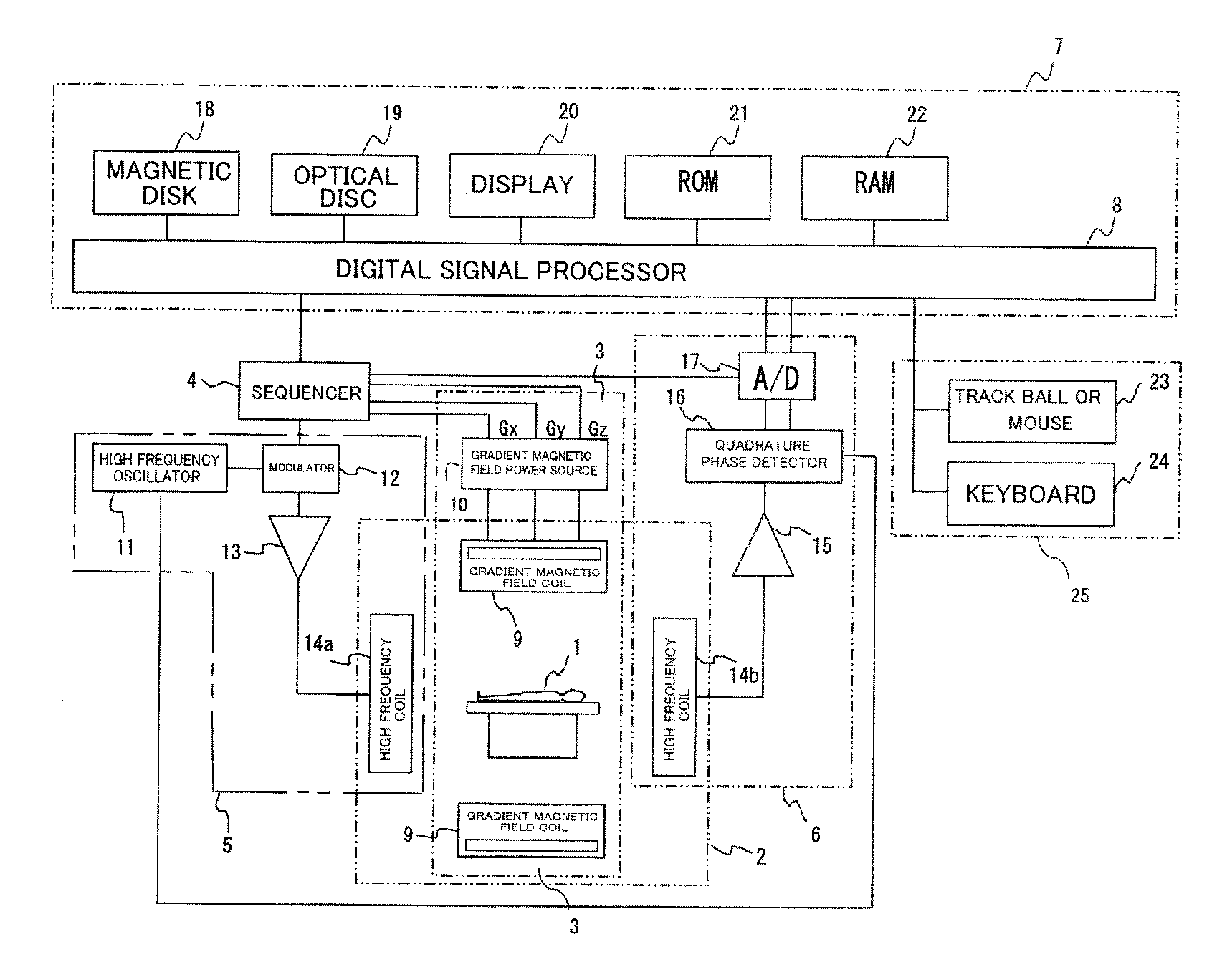
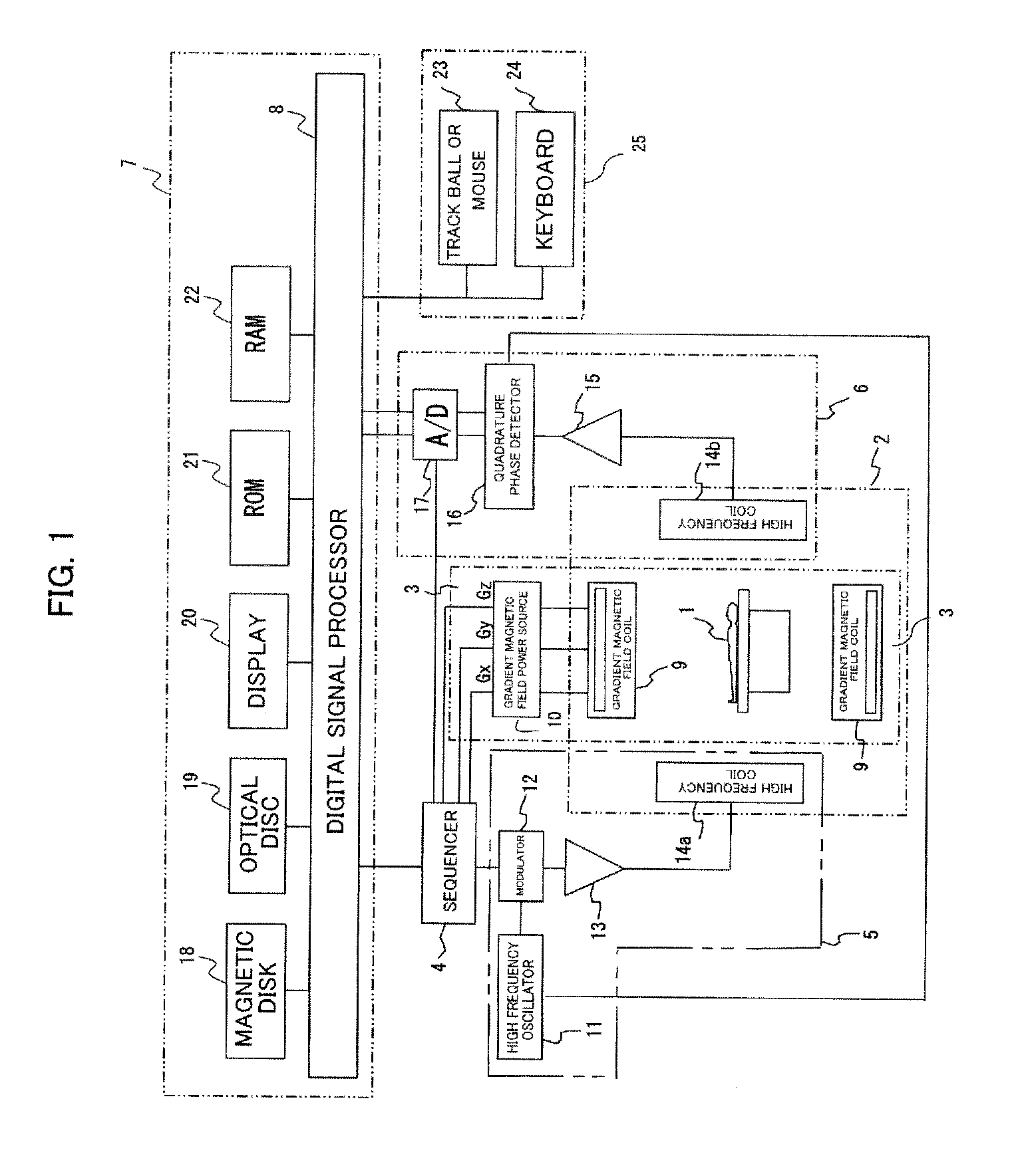
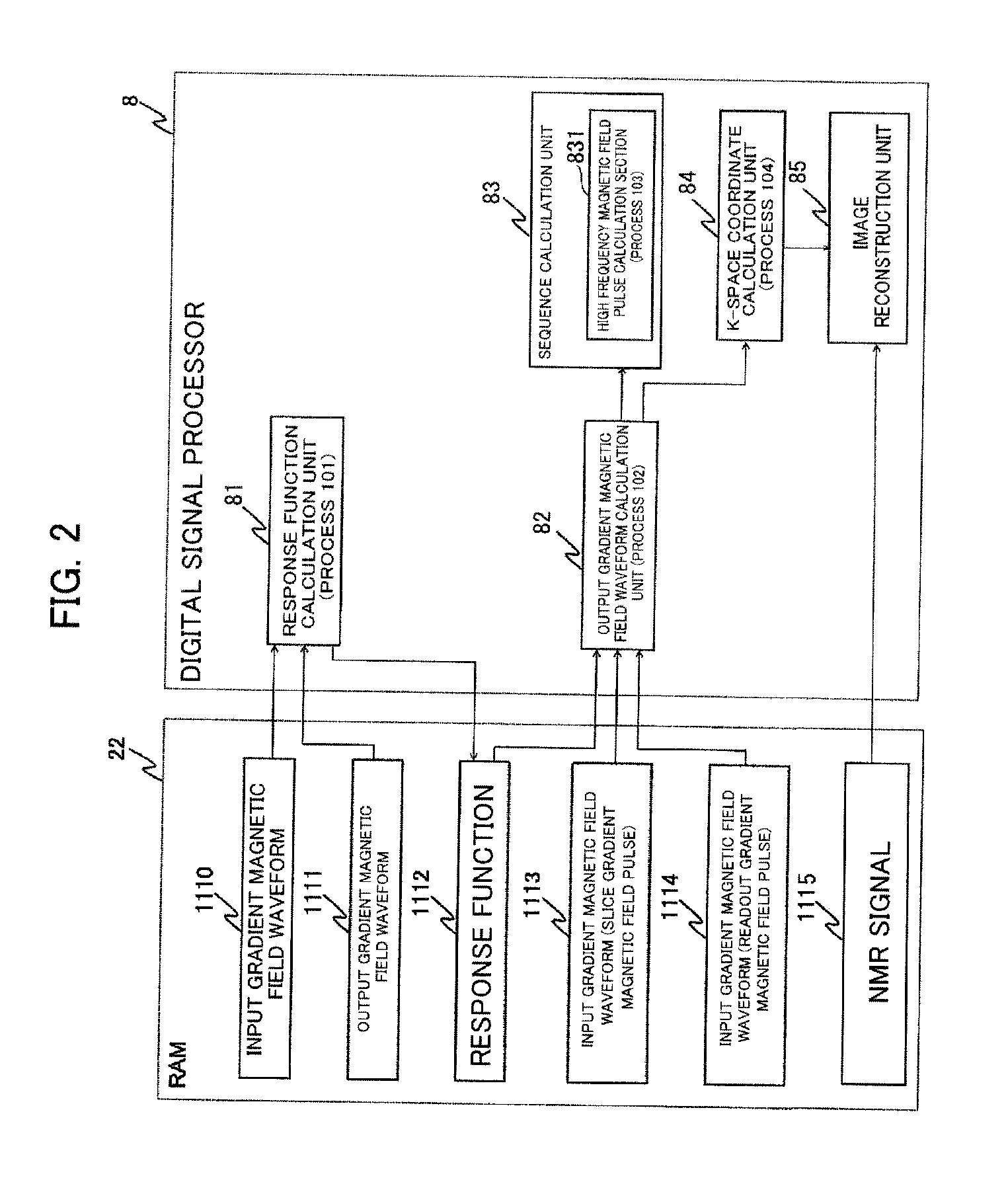
[0060]The process performed by the digital signal processor 8 of the MRI apparatus of the present embodiment is largely divided into four processes. The relationship of the four processes will be described with reference to the block diagram of FIG. 2. A first process 101 is a process performed by the response function calculation unit 81 as a preliminary measurement, and is a process of calculating response functions 1112 of eddy current and a control circuit of a gradient magnetic field power source. Processes 102 to 104 are processes performed in actual imaging. The process 102 is a process of estimating each output gradient magnetic field waveform using the response function 1112 calculated by the process 101 and input gradient magnetic field waveforms 1113 and 1114 set for each imaging sequence, and is performed by the gradient magnetic field waveform calculation unit 82. The process 103 is a process of recalculating an imaging sequence high frequency magnetic field pulse using...
second embodiment
[0134]Also in the present embodiment, the configuration of the digital signal processor 8 shown in FIG. 2 and the four characteristic processes 101 to 104 performed by the digital signal processor 8 are the same as those in the first embodiment.
[0135]The present embodiment is characterized in that the process 101 of calculating the response functions of the eddy current and the control circuit of the gradient magnetic field power source is performed in a simpler procedure than in the first embodiment. That is, in the first embodiment, measurement of the output gradient magnetic field waveform has been performed twice in a state where the control of the gradient magnetic field power source circuit is disabled and a state where the control of the gradient magnetic field power source circuit is enabled. In the present embodiment, however, the measurement of the output gradient magnetic field waveform is performed only once. The flow of the process of the present embodiment will be desc...
third embodiment
[0146]Also in the present embodiment, the configuration of the digital signal processor 8 shown in FIG. 2 and the four processes 101 to 104 performed by the digital signal processor 8 are the same as those in the first embodiment. The present embodiment is characterized in that the response functions of the eddy current and the control circuit of the gradient magnetic field power source are calculated without specific model expressions being applied. FIG. 18 shows the flow of the process of the present embodiment. Although steps 1801 and 1802 in FIG. 18 are the same as the steps 1601 and 1602 in FIG. 16 described in the second embodiment, processing unique to the present embodiment is processing of measuring the output gradient magnetic field waveform using a plurality of kinds of input gradient magnetic field waveforms in step 1801, processing of directly deriving the response functions of the eddy current and the gradient magnetic field control circuit without using any model expr...
PUM
 Abstract
Description
Claims
Application Information
 - R&D
- Intellectual Property
- Life Sciences
- Materials
- Tech Scout
- Unparalleled Data Quality
- Higher Quality Content
- 60% Fewer Hallucinations
Browse by: Latest US Patents, China's latest patents, Technical Efficacy Thesaurus, Application Domain, Technology Topic, Popular Technical Reports.
© 2025 PatSnap. All rights reserved.Legal|Privacy policy|Modern Slavery Act Transparency Statement|Sitemap|About US| Contact US: help@patsnap.com


