Spatially distributed laser resonator

a laser resonator and spatially distributed technology, applied in the direction of optical resonator shape and construction, electromagnetic transmission, transmission, etc., can solve the problems of beam propagation, field of view, components of the laser system might not have the optimum or the required size or field of view

Active Publication Date: 2014-05-08
WI CHARGE
View PDF4 Cites 17 Cited by
  • Summary
  • Abstract
  • Description
  • Claims
  • Application Information

AI Technical Summary

Benefits of technology

[0015]a) Allows for retro reflection along the incident beam's path, so that the incoming and returning beams travel along the same path. This feature enables the distributed laser to operate with the beams in a co-linear mode, instead of the ring mode described in the prior art.
[0050]In addition, the system may be designed to have other regions, other than at pupil positions, at which beams coming from different angles will be optically directed to traverse those regions parallel to each other (i.e. telecentric regions), enabling the placement of optical components which should operate independently of the angle of incidence of the beam on the input lens.

Problems solved by technology

However, such retro-reflectors may generate aberrations and other beam propagation problems such as focusing or defocusing, excitation of higher-order beams, or other artifacts, which need to be treated in order to ensure consistent quality lasing at acceptable power conversion efficiencies and within accepted safety standards.
In addition, use of such retroreflectors may limit the field of view, which therefore may need to be increased optically to make the system of practical use.
Additionally, components of the laser system might not have the optimum or the required size or field of view, which may be corrected using an additional optical system within the laser cavity.
Using prior art distributed laser resonators having a double beam geometry, the insertion of additional optical components into the beam was ineffective because of this double beam geometry.

Method used


Image

  • Spatially distributed laser resonator
  • Spatially distributed laser resonator
  • Spatially distributed laser resonator

Examples


Embodiment Construction

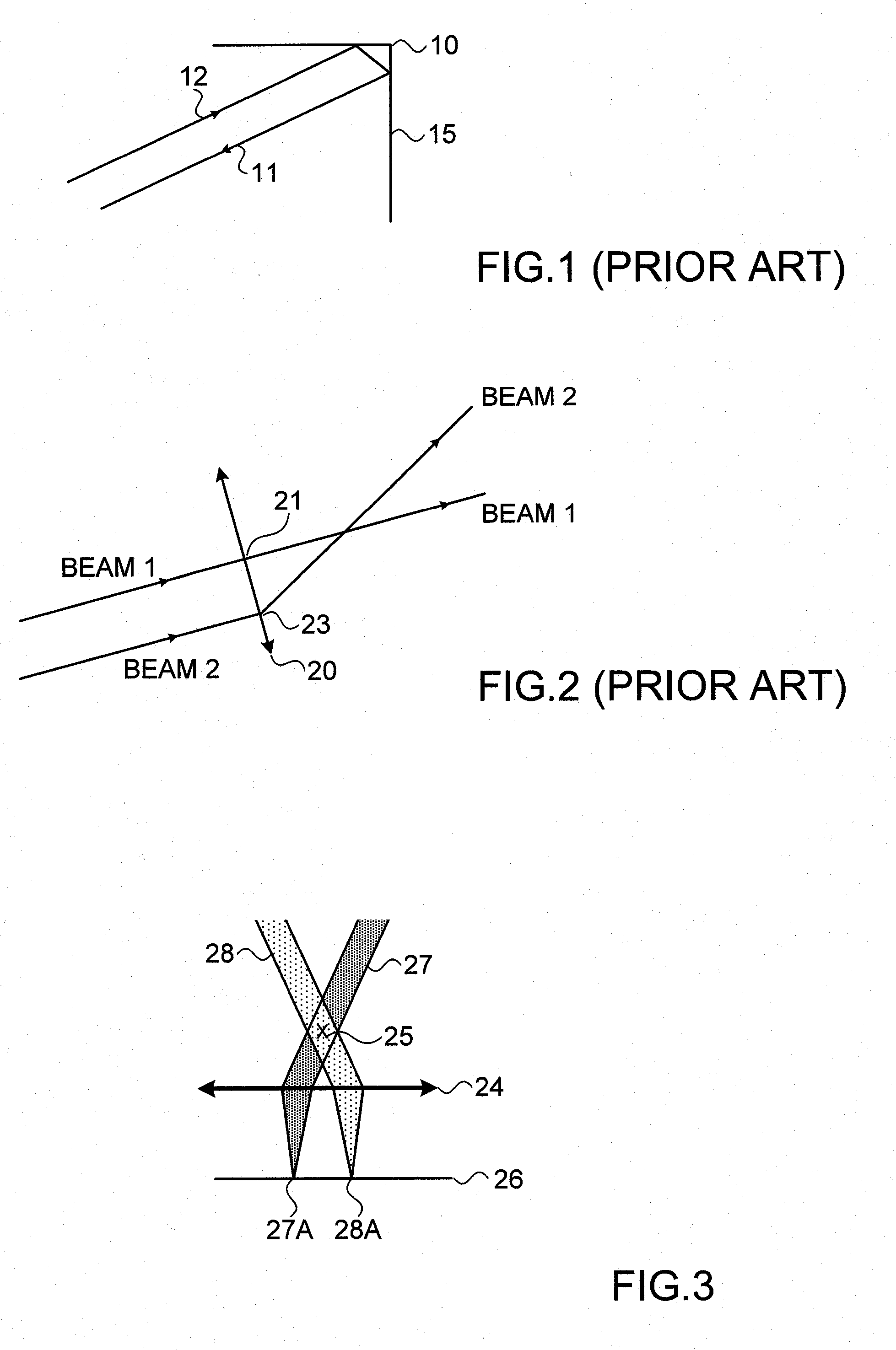
[0085]Reference is first made to FIG. 3, which is provided to illustrate one way in which pupils, or pupil planes and pupil imaging can be visualized, in order to clarify graphically the explanations thereof given in the Summary section of this disclosure. In FIG. 3, a lens 24 is positioned in space. All collimated beams passing through the pupil 25 form an image spot on the image plane 26. For example collimated beam 27 will be focused on point 27a on the imaging plane, while collimated beam 28 will form a focused image spot 28a on imaging plane 26.

[0086]If the system would be designed or set up to handle uncollimated beams with a certain radius of curvature, the imaging plane would move in space, but would still exist. The imaging plane is not necessarily flat. In this application the area in the vicinity of the pupil having a width essentially similar or slightly larger than the beam width, is termed “the pupil”, and the plane at which the beams are focused the “imaging plane”.

[0...


PUM


Abstract

A distributed resonator laser system using retro-reflecting elements, in which spatially separated retroreflecting elements define respectively a power transmitting and a power receiving unit. The retroreflectors have no point of inversion, so that an incident beam is reflected back along a path essentially coincident with that of the incident beam. This enables the distributed laser to operate with the beams in a co-linear mode, instead of the ring mode described in the prior art. This feature allows the simple inclusion of elements having optical power within the distributed cavity, enabling such functions as focusing / defocusing, increasing the field of view of the system, and changing the Rayleigh length of the beam. The optical system can advantageously be constructed as a pupil imaging system, with the advantage that optical components, such as the gain medium or a photo-voltaic converter, can be positioned at such a pupil without physical limitations.

Description

FIELD OF THE INVENTION[0001]The present invention relates to the field of distributed laser resonators using retroreflectors, especially for use in systems for wireless transmission of power to portable electronic devices by means of intracavity laser power.BACKGROUND OF THE INVENTION[0002]In the PCT application PCT / IL2006 / 001131, published as WO2007 / 036937 for “Directional Light Transmitter and Receiver” and in the PCT application PCT / IL2009 / 000010, published as WO / 2009 / 008399 for “Wireless Laser Power” there are shown wireless power delivery systems based on distributed laser resonators. This term is used in the current disclosure to describe a laser having its cavity mirrors separated in free space, and without any specific predefined spatial relationship between the cavity mirrors, such that the laser is capable of operating between randomly positioned end reflectors. In the above mentioned applications, one use of such distributed laser resonators is in transmitting optical pow...

Claims


Application Information

Patent Timeline
Patent Type & Authority Applications(United States)
IPC IPC(8): H01S3/06
CPCH01S3/0627H02J3/383H01S3/0014H01S3/005H01S3/0604H01S3/08H01S3/0805H01S3/08054H01S3/0813H01S3/1611H01S3/1643H04B10/807H01S3/0815Y02E10/56H02J50/30
Inventor DELLA-PERGOLA, REFAELALPERT, ORTALNAHMIAS, OMERVAISLEIB, VICTOR
Owner WI CHARGE
Why Eureka
Try Eureka