Testing apparatus and method for MIMO systems

a technology of testing apparatus and mimo, which is applied in the direction of transmission monitoring, receiver monitoring, line-transmission details, etc., can solve the problems of 22 mimo scheme, difficult to modify existing testing apparatuses that have a testing function, etc., and achieve the effect of low cost structure and easy modification

Active Publication Date: 2014-05-08
ANRITSU CORP
View PDF4 Cites 13 Cited by
  • Summary
  • Abstract
  • Description
  • Claims
  • Application Information

AI Technical Summary

Benefits of technology

[0022]It is an object of the invention to provide a testing apparatus, which overcomes the above-mentioned problems to thereby realize tes...

Problems solved by technology

Further, it is difficult to modify existing testing apparatuses that have a testing function corresponding to the 2×2 M...

Method used


Image

  • Testing apparatus and method for MIMO systems
  • Testing apparatus and method for MIMO systems
  • Testing apparatus and method for MIMO systems

Examples


Embodiment Construction

[0067]Various embodiments will be described hereinafter with reference to the accompanying drawings.

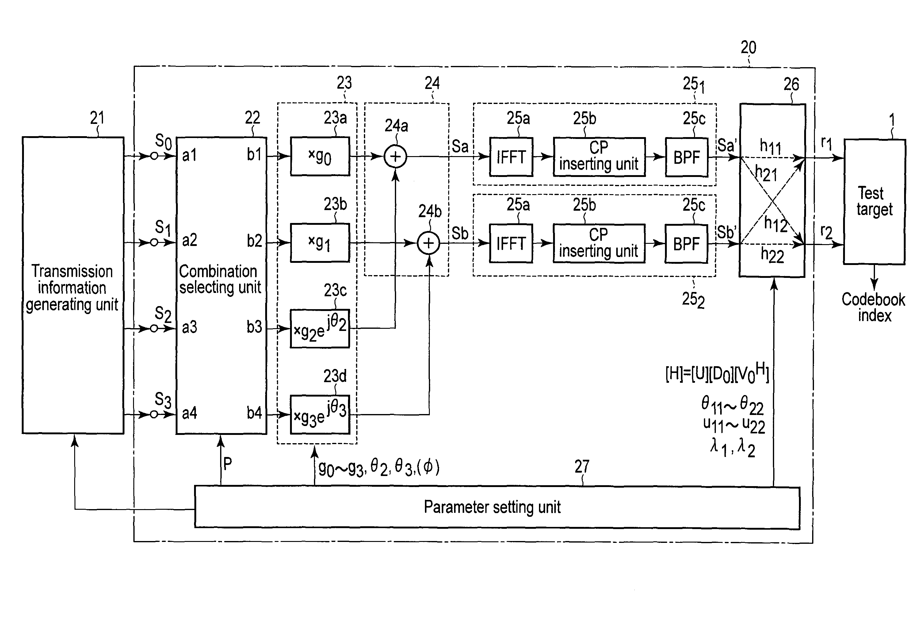
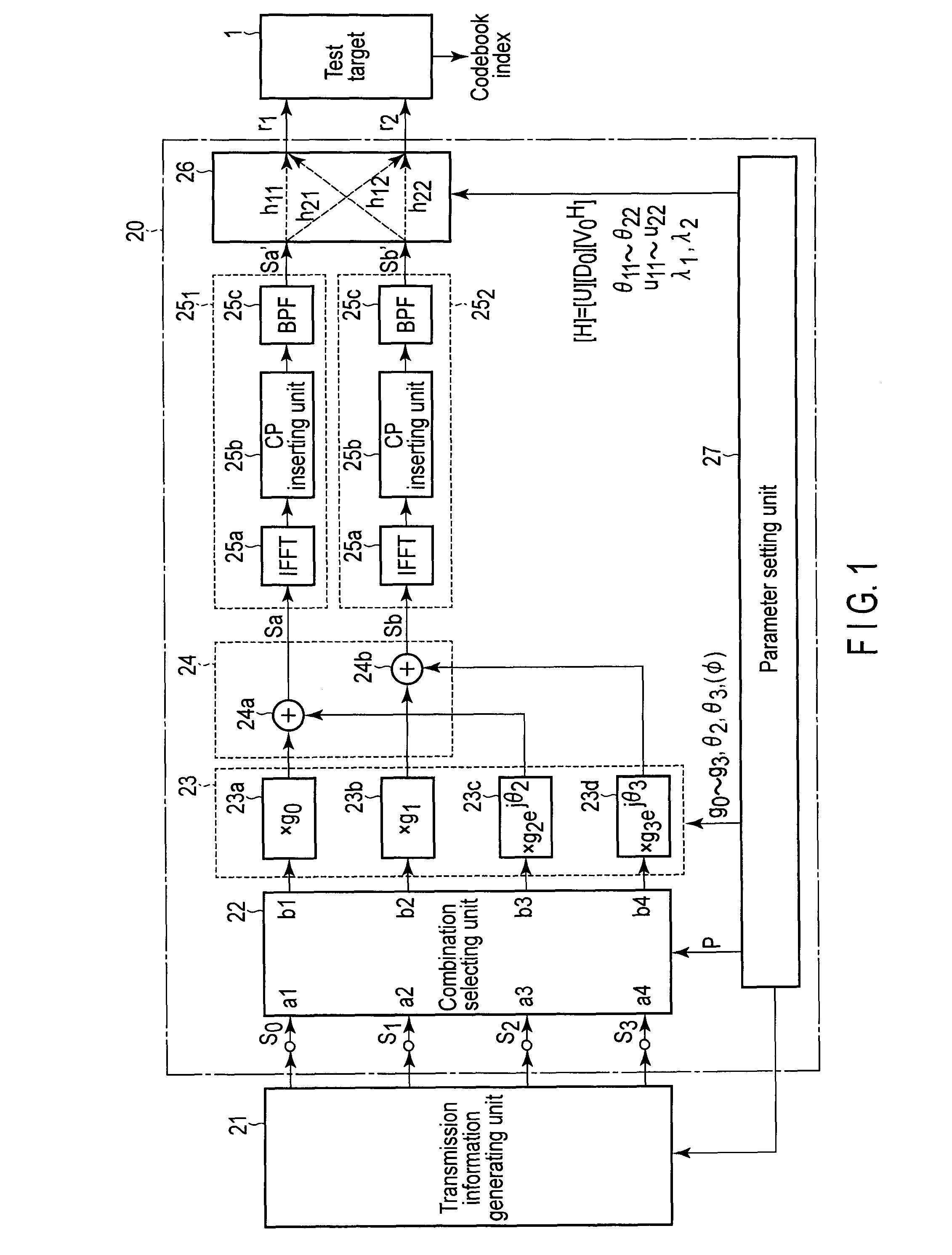
[0068]FIG. 1 shows the configuration of a testing apparatus 20 for M×N (M>N) MIMO systems, according to an embodiment of the invention. The testing apparatus 20 of the embodiment is of M×N (M=4, N=2) type.

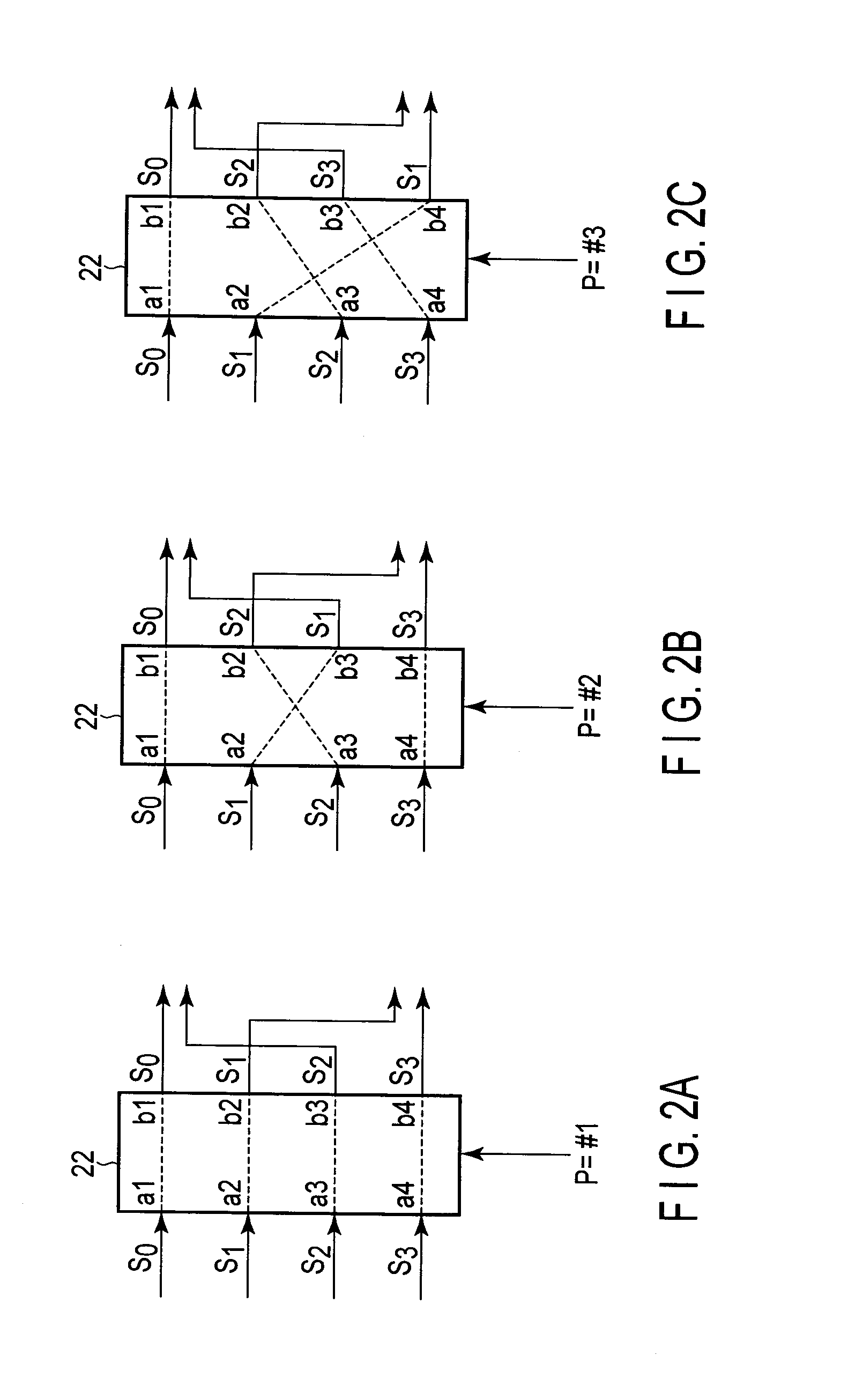
[0069]The testing apparatus 20 comprises a transmission information generating unit 21, a combination selecting unit 22, a phase shift unit 23, an additive synthesis unit 24, two (=N) signal processing units 251 and 252, a 2×2 (=N×N) propagation channel processing unit 26 and a parameter setting unit 27.

[0070]The transmission information generating unit 21 generates and outputs four (=M) transmission information signals s0 to s3 to be transmitted to a test target 1. The transmission information signals s0 to s3 are source signals unique to a modulation technique. For instance, in the case of the modulation technique OFDMA for use in LTE or the modulation technique OFDM for use in wir...


PUM


Abstract

Four (=M) transmission information signals are output from transmission information generating unit to linear transform unit, where they are transformed into synthesis signals by linear transform expressed by multiplication by a 2×4 matrix having complex numbers as elements. Signal processors perform signal processing corresponding to the modulation technique of test target on synthesis signals. On the resultant signals, 2×2 channel processing unit performs 2×2 pseudo channel processing, thereby forming equivalent M×N channels. Parameter setting unit sets information necessary to acquire desired M×N channel characteristics as the synthesis characteristics of linear transform unit and N×N channel processing unit.

Description

CROSS-REFERENCE TO RELATED APPLICATIONS[0001]This application is based upon and claims the benefit of priority from prior Japanese Patent Application No. 2012-245082, filed Nov. 7, 2012, the entire contents of which are incorporated herein by reference.BACKGROUND OF THE INVENTION[0002]1. Field of the Invention[0003]The present invention relates to a testing apparatus and method for MIMO systems. In particular, the invention relates to a testing apparatus and method for M×N MIMO (Multiple Input Multiple Output) systems that generate signals equivalent to those transmitted through M×N propagation channels and apply the generated signals to a mobile terminal as a test target, such as a mobile phone utilizing the MIMO scheme, or a circuit board contained therein, or an integrated circuit mounted on the board, in order to check them. More specifically, the invention relates to a testing apparatus and method for MIMO systems, in which while the M×N MIMO scheme is maintained theoretically,...

Claims


Application Information

Patent Timeline
IPC IPC(8): H04B17/00H04B7/04H04B17/29H04B17/391H04J11/00H04J99/00
CPCH04B7/0456H04B17/009H04B17/391
Inventor KOBAYASHI, TAKESHIKITAGAWA, KAZUNORIHIZUME, MASAKI
Owner ANRITSU CORP
Why Eureka
Try Eureka