High solids enzyme reactor mixer with vertical paddle and method

a technology of enzyme reactor and mixer, which is applied in the direction of rotary stirring mixer, transportation and packaging, and enzyme production/based bioreactor, etc., can solve the problems of rotation deltas throughout the length of the mixing chamber, and achieve the effect of promoting plug flow, reducing rotation deltas, and slowing down the ra

Inactive Publication Date: 2014-05-08
ANDRITZ INC
View PDF6 Cites 19 Cited by
  • Summary
  • Abstract
  • Description
  • Claims
  • Application Information

AI Technical Summary

Benefits of technology

[0013]The biomass and enzyme material tends to rotate at a slower rate than the paddles because of the drag of the biomass and enzyme material. As the biomass and enzyme material slowly descends down the mixing chamber of the reactor vessel, the enzymes react with the biomass and the viscosity of the biomass and enzyme material changes. Unfortunately, as the viscosity of the biomass and enzyme material changes, so do the drag and the rotation speed of the biomass and enzyme material, which causes rotation deltas throughout the length of the mixing chamber. The inventors have recognized that vertical paddles having a varying hydrofoil cross-section or angle of attack may be used to keep the rotation of the biomass and enzyme material substantially constant over the entire length of the mixing chamber. This design may promote plug flow and reduce rotation deltas.
[0014]To promote plug flow, improve mixing, and reduce stagnant regions in the mixing chamber of the reactor vessel, a new vertically-oriented paddle with a hydrofoil shape has been conceived for mixing biomass and enzyme material. In example embodiments, the “angle of attack” (i.e. the angle at which the paddle engages the biomass and enzyme material) may vary along the length of the paddle. In other embodiments, the cross-sectional area of the paddle along a horizontal plane may vary along the length of the paddle.
[0015]It is desirable to have a slow and uniform plug flow of material vertically down the mixing chamber of the reactor vessel. A slow, constant plug flow movement may be desirable to ensure a less aggressive mixing than in the prior art vessels where mixing occurred resulting in material from a lower elevation in the mixing chamber being pushed up the mixing chamber, thus disrupting plug flow. Rather than moving biomass and enzyme material up in the mixing chamber of a reactor vessel, a horizontal blending of the biomass and enzyme material at all vertical positions within the mixing chamber may reduce areas of stagnant material.

Problems solved by technology

Unfortunately, as the viscosity of the biomass and enzyme material changes, so do the drag and the rotation speed of the biomass and enzyme material, which causes rotation deltas throughout the length of the mixing chamber.

Method used


Image

  • High solids enzyme reactor mixer with vertical paddle and method
  • High solids enzyme reactor mixer with vertical paddle and method
  • High solids enzyme reactor mixer with vertical paddle and method

Examples


Embodiment Construction

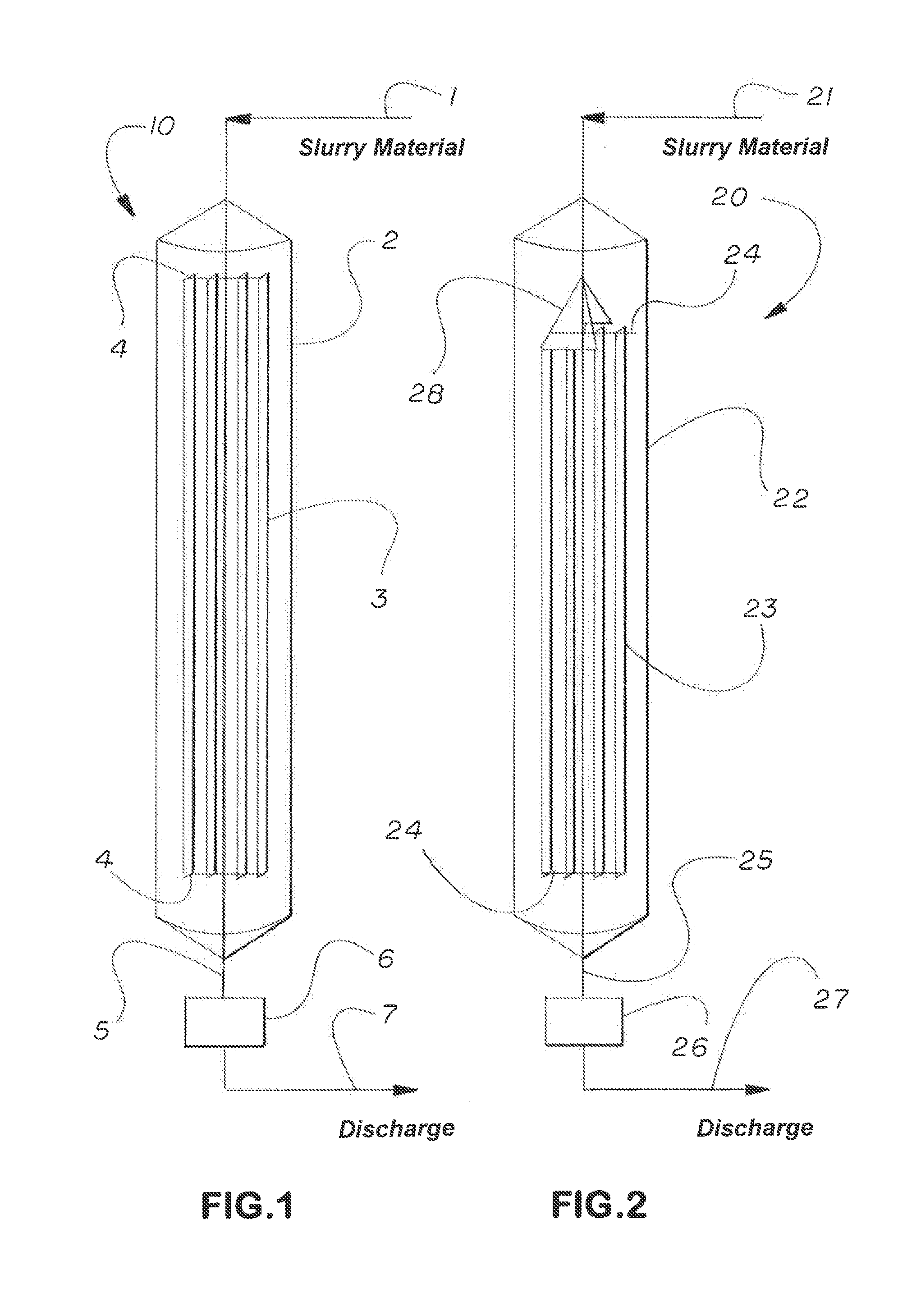
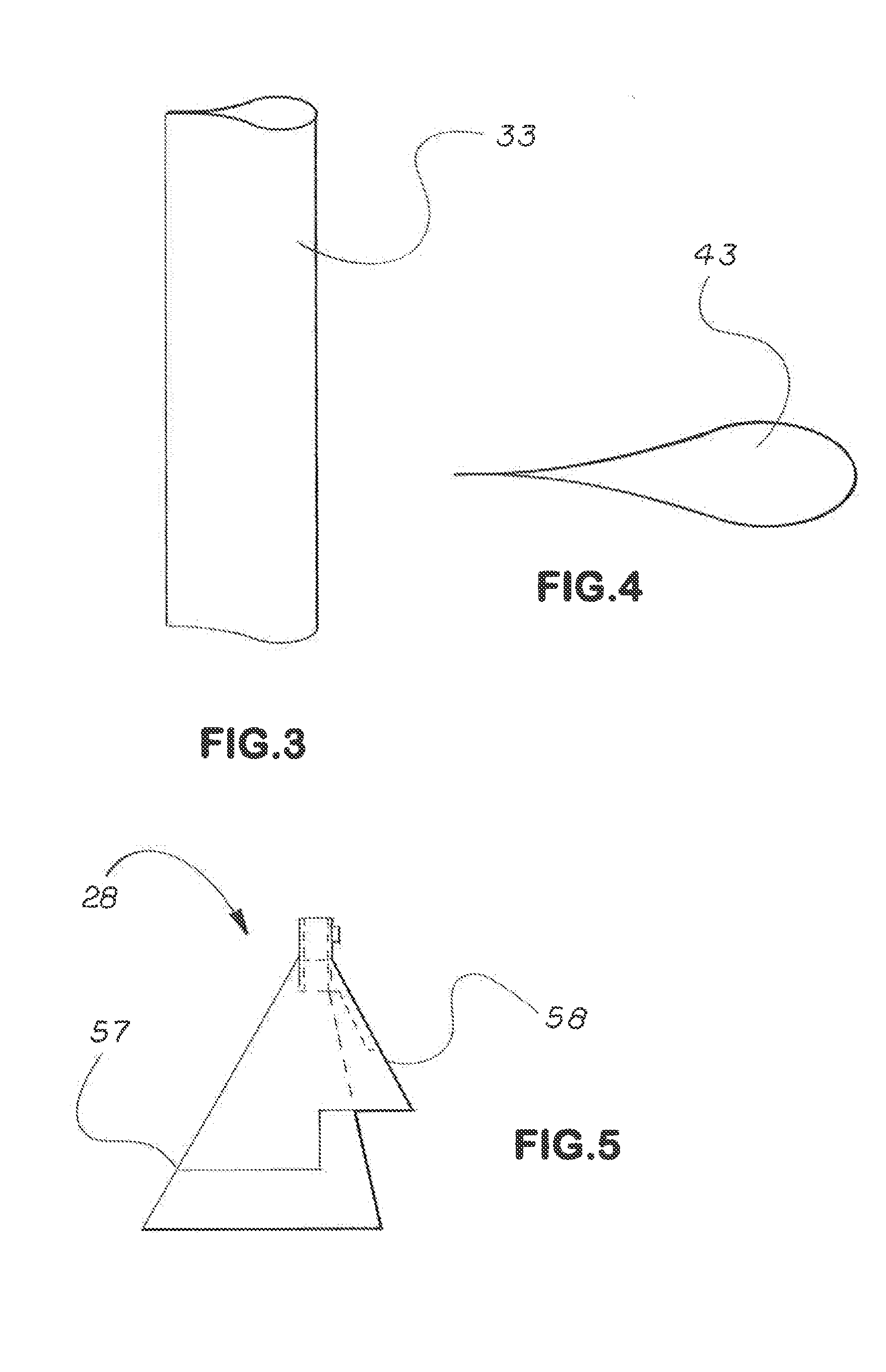
[0048]The flow cone may be attached to the center shaft and may be positioned to allow the support bar at the top end of the paddles to fit at the bottom of the flow cone or just inside the flow cone. Because the flow cone is attached to the center shaft, it moves in the same motion of the center shaft. As slurry material of biomass and enzymes enters the mixing chamber, the slurry material of biomass and enzymes contacts the flow cone and moves along outer surface of the flow cone. The flow cone may direct the flow of the slurry material of biomass and enzymes entering the vessel to all parts of the body of the mixing chamber. The flow cone may also distribute the flow of slurry material and biomass along the circular area of the mixing chamber without preference to any one area of the mixing chamber. As a result, the flow cone may form a thick padding-like layer along the surface of the mixing chamber to avoid liquid less fully incorporated in the slurry from gathering along the i...


PUM

PropertyMeasurementUnit
diameteraaaaaaaaaa
diameteraaaaaaaaaa
offset angleaaaaaaaaaa

Abstract

A reactor vessel including: a mixing chamber having a vertical length, an upper inlet, and a lower outlet; and a vertically oriented paddle within the mixing chamber and having a cross-sectional shape of a hydrofoil, wherein the paddle moves with respect to the mixing chamber.

Description

RELATED APPLICATION[0001]This application claims priority to and incorporates by reference provisional Application 61 / 723,538 filed Nov. 7, 2012.TECHNICAL FIELD[0002]Example embodiments of the invention relate generally to the field of enzymatic conversion of biomass to monomeric sugars and particularly to mixing the biomass with enzymes to promote hydrolysis.BACKGROUND OF THE INVENTION[0003]Biomass feedstock may be solely lignocellulosic material or a mixture of lignocellulosic and other materials. Polysaccharide biomass is typically a mixture of starch and lignocellulosic materials. The starch may be contained in grains or a refined starch added as feedstock to form the biomass. The biomass feedstock may also include polymers and other materials.[0004]Enzymes are mixed with the biomass to promote hydrolysis. Mixing ensures the enzymes continually and repeatedly move into contact with chemical reaction sites in the biomass to promote hydrolysis or other degradation of the biomass. ...

Claims


Application Information

Patent Timeline
Patent Type & Authority Applications(United States)
IPC IPC(8): C12P19/14B01F7/16C12P19/02B01F7/18
CPCC12P19/14C12P19/02B01F7/18B01F7/1675C12M21/18C12M23/40C12M27/02C12M27/20C12M39/00C12M45/09B01F27/86B01F27/90
Inventor BOLZ, EDWIN WILLIAMROMERO, RODOLFO
Owner ANDRITZ INC
Why Eureka
Try Eureka