Drive unit, elevator and method for driving elevator

a technology of drive unit and elevator, which is applied in the field of elevators, can solve the problems of lifetime problems, extra costs and standstills, and slow down the service of jobs

Active Publication Date: 2014-05-15
KONE CORP
View PDF11 Cites 15 Cited by
  • Summary
  • Abstract
  • Description
  • Claims
  • Application Information

AI Technical Summary

Benefits of technology

[0012]In one preferred embodiment of the invention the driving member is configured to be fixed to the transmission means of the drive unit with a quick-release fastener. The quick-release fastener is, in its basic principles, a fastening means known in the art, by using which the drive unit can be connected to the driving member in the elevator quickly and reliably and can also be detached from the driving member quickly, in which case placing the elevator into operating condition / disassembly of the apparatus can occur quickly and conveniently. A shaft with a keyway, a splined shaft or some other multi-angular shaft fitting, for example, can also be used in the fixing between the driving member and the transmission means of the drive unit. Other connection methods known in the art, such as a crimped joint, magnetic joint, bolted joint or hexagonal joint or corresponding, can also be used for the fixing.
[0029]In a preferred embodiment of the invention the aforementioned transmission means of the drive unit is configured to be fixed to the driving member. The transmission means can be connected to the driving member directly or e.g. via a gear, preferably via a reduction gear, or by belt friction via a separate drive belt and traction sheave. In some embodiments a gear is disposed in the drive unit; it is however advantageous to dispose the gear outside the drive unit in a fixed manner on a part of the elevator situated at the operating location, because then the size and weight of the drive unit decrease and transfer of the drive unit becomes easier.
[0036]In some embodiments of the invention, the drive unit and the machine bedplate are shaped such that the drive unit cannot be lowered into its position in the machine bedplate before the drive unit is fitted into position in connection with the driving member or, alternatively, such that a connection between the drive unit and the driving member is not possible if the drive unit is not in its position in the machine bedplate. In this way by the aid of just one safety switch, or even without separate safety switches, it can be ensured that the drive unit is connected to be properly attached to the driving member as well as to the machine bedplate.
[0039]In one preferred embodiment of the invention the aforementioned one or more sensors determining the connection status of the drive unit are connected in the drive unit with a signal wire to the safety circuit of the elevator. In this way a safety circuit can be formed also in solutions in which the safety circuit is disposed wholly in the drive unit. Since the aforementioned sensor(s) as well as other electronic and electrical components, with their wiring, that possibly belong to the safety circuit are often sensitive to stressing caused by the environment, by situating the safety circuit in the drive unit the reliability problem and safety problem caused by environmental stressing can be reduced.
[0041]In one preferred embodiment of the invention the drive unit comprises a control unit of an elevator. Also the control unit of an elevator comprises components that are susceptible to damage owing to the stressing of the environment. In a preferred embodiment of the invention the control unit of the elevator comprises a microprocessor and also a memory, in which elevator control functions and / or algorithms to be run on the microprocessor can be saved.
[0050]The elevator according to the invention is extremely well suited for use, in addition to wind power stations, also in e.g. radio masts, oil drilling platforms, construction sites, lighthouses, and in other such sites in which an elevator tower / hoistway is at least partly open or otherwise subjected to demanding environmental conditions. This is because of the fact that by means of the invention the reliability problems / malfunctioning problems caused by demanding environmental stresses, such as atmospheric moisture, salinity, cold, heat, snow / ice, solar radiation, wind, water, dirt, construction dust, et cetera, on the sensitive components of the drive unit, such as on the motor windings, bearings, solid-state switches, safety switches, control cards or uninsulated connections, can be reduced.

Problems solved by technology

Owing to this, atmospheric moisture, salinity, cold, heat, solar radiation, wind, dirt and many other factors cause lifetime problems especially for the electric drive, control cards and other particularly sensitive components.
Since many of the sites are located at the end of difficult transport connections, spare parts deliveries are also slow, slowing down servicing jobs and thus causing extra costs and standstills.
Each aforementioned elevator in this case forms a potential reliability problem slowing down servicing.
This, however, incurs additional costs and is otherwise often unreasonably awkward precisely because of, inter alia, the awkward transport connections.
In addition, protection in different operating sites essentially intended to be open can even be impossible.

Method used


Image

  • Drive unit, elevator and method for driving elevator
  • Drive unit, elevator and method for driving elevator
  • Drive unit, elevator and method for driving elevator

Examples


embodiment 1

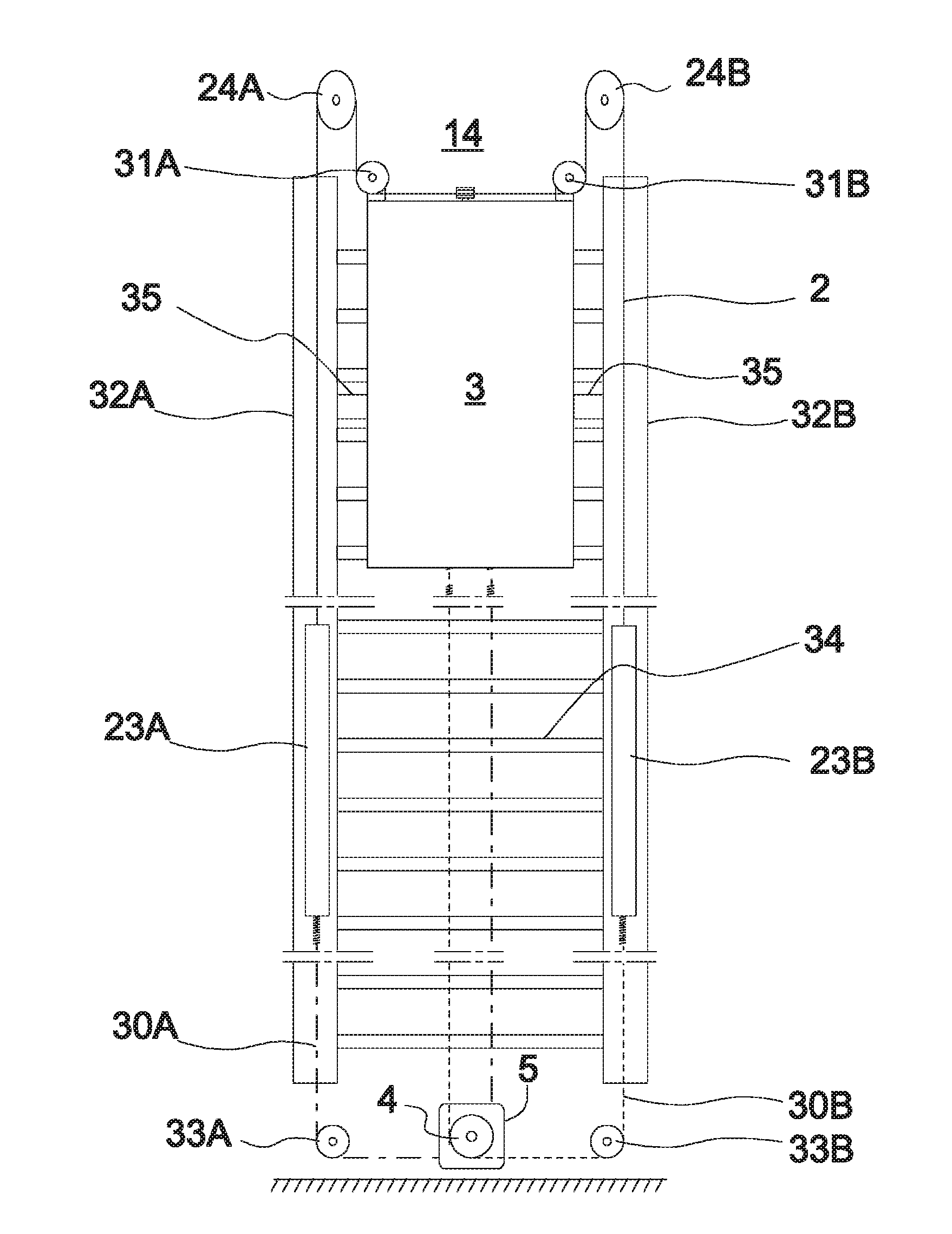
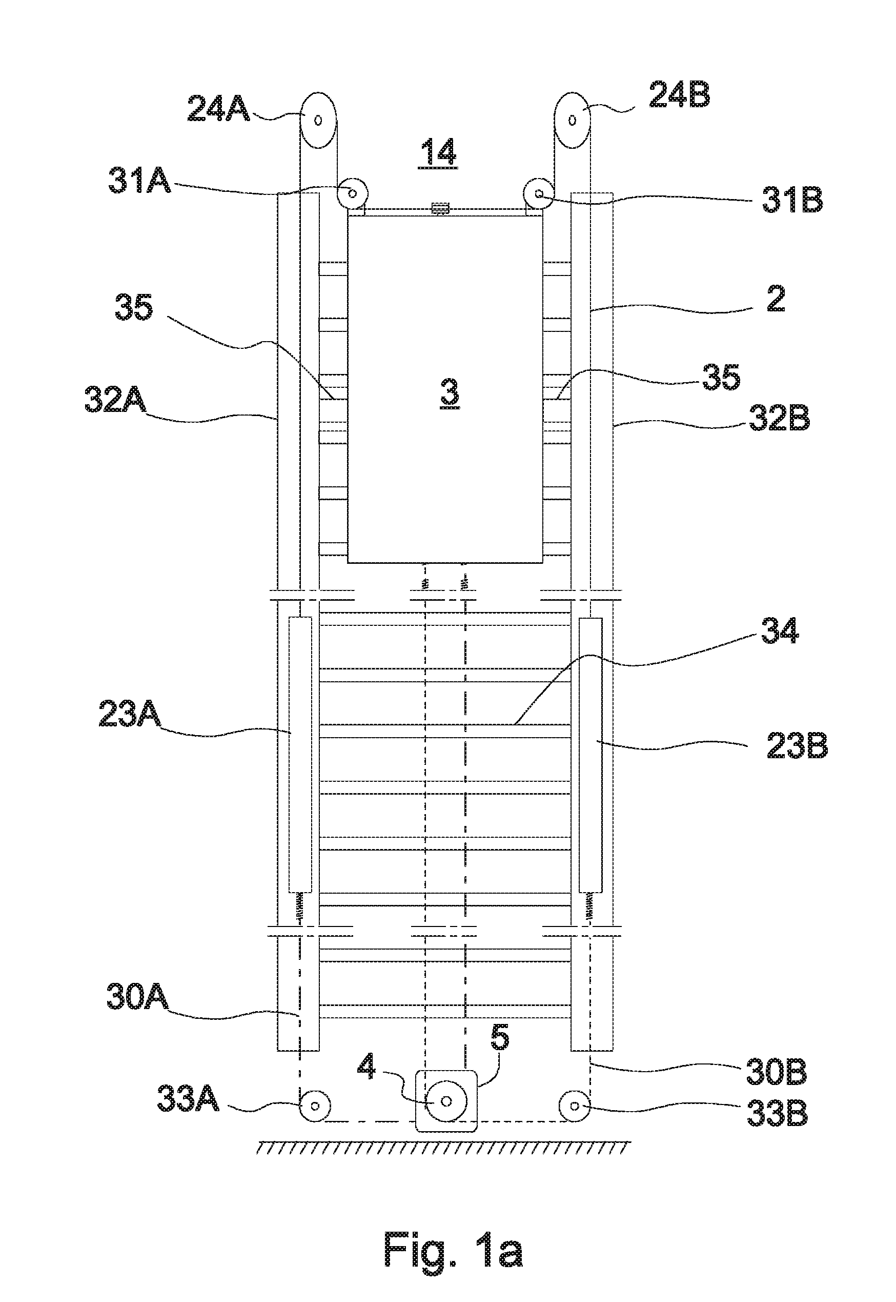
[0061]The elevator presented in FIG. 1a can function e.g. as a service elevator of a wind power station 13 according to FIG. 4. The elevator car 3 in FIG. 1 is suspended in the elevator car 14 on a cable 2, which travels from diverting pulleys 31A, 31B fixed in a manner allowing rotation to the top part of the elevator car 3 via diverting pulleys 24A, 24B fixed in a manner allowing rotation to a supporting structure in the top part of the elevator tower 14 downwards by the sides of the elevator car 3 along parallel hollow profiles 32A, 32B and are fixed to compensating weights 23A, 23B, which also travel in the aforementioned hollow profiles 32A, 32B. Fixed to the compensating weights 23A, 23B are also belts 30A, 30B, which travel in the same hollow profiles 32A, 32B downwards from the compensating weights 23A, 23B via diverting pulleys 33A, 33B fixed in a manner allowing rotation to a supporting structure of the bottom end zone of the elevator tower to the traction grooves of the t...

embodiment 2

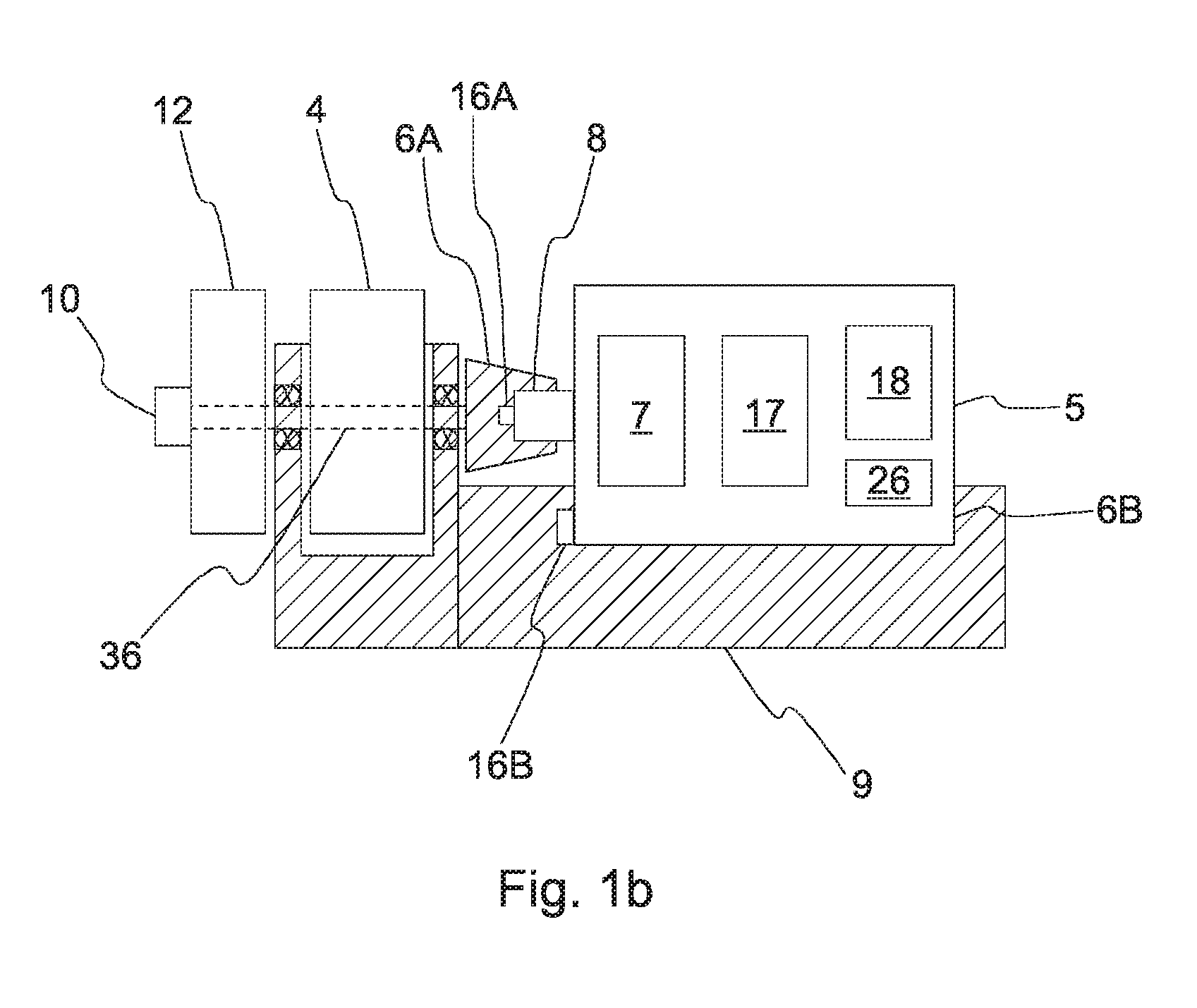
[0069]The elevator 1 of FIG. 2 differs from the elevator presented in FIG. 1a in that the elevator car 3 is suspended on a cable 2 in the elevator 14, which cable travels downwards from the elevator car 3 via a diverting pulley 24 in the top part of the elevator tower 14 to a drum collecting, distributing cable 2 as it rotates, said drum being in the bottom end zone of the elevator tower 14. The elevator car 3 moves when the drum 4 is rotated with a drive unit 5 temporarily fixed to the drum 4. In addition, in connection with the drum 4 are one or more controllable machinery brakes 12, which when activated engage mechanically with the braking surface of the drum / drum shaft to brake the movement of the drum 4. The elevator car is controlled with a separate control cable 41, to which the elevator car 3 is connected with a controller 40.

[0070]The drive unit 5 is in its basic principles according to embodiment 1, comprising the same functional parts; also the fixing of the shaft of the ...

embodiment 3

[0071]The elevator 1 of FIG. 3 differs from the elevators of FIGS. 1a and 2 in that a detachable drive unit 5 is fixed to a traction sheave 4 supported on the roof of the elevator car 3 in a manner allowing rotation, in connection with the traction sheave 4 via a reduction gear (not in figure). The elevator car 3 is suspended on a cable 2 by circulating the cable 2 once around a traction sheave 4. The cable 2 running in a vertical direction in the elevator tower 14 is fixed in position at its top end and at its bottom end on a supporting structure of the elevator tower 14. The drive unit 5 is in its basic principles according to embodiments 1 or 2, comprising the same functional parts; also the fixing of the shaft 8 of the electric motor in the drive unit 5 onto a rotating traction sheave 4 is of the same type as the fixing between the shaft 8 and the traction sheave / drum 4 in embodiments 1 or 2. The drive unit 5 is also fixed to a supporting structure of the roof of the elevator ca...


PUM


Abstract

An elevator and also to a drive unit for driving an elevator includes one or more hoisting members that are continuous in the vertical direction, a load-receiving part suspended on the hoisting member, and also a driving member engaging with the hoisting member for moving the load-receiving part. The driving member engaging with the hoisting member is configured to be driven with a detachable drive unit.

Description

FIELD OF THE INVENTION[0001]The invention relates to elevators, more particularly to methods for connecting and operating the drive units of elevators.BACKGROUND OF THE INVENTION[0002]The servicing work, installation work and repair work of an object to be serviced, such as a wind power station, an oil drilling platform, a lighthouse, et cetera, usually requires that the object comprises an elevator, with which it is possible to move and to lift a load in the vertical direction. The structure of this type of elevator can vary, but the elevator usually comprises an elevator car, a lifting platform or corresponding load-receiving part, with which a load is transferred. The load-receiving part is suspended on a hoisting member that is continuous in the vertical direction, such as on a hoisting rope or hoisting belt. The load-receiving part is moved along a vertical trajectory guided by a guide rail, a guide cable or corresponding. In some embodiments the hoisting member is also used as...

Claims


Application Information

Patent Timeline
Patent Type & Authority Applications(United States)
IPC IPC(8): B66B11/04F03D11/04E04H12/00
CPCB66B11/04F03D11/04E04H12/00B66B9/00B66B9/187F03D80/00F03D13/20Y02E10/728F03D13/40F03D80/50Y02E10/72B66B1/00H02K7/10H02K7/14
Inventor TALONEN, TAPANI
Owner KONE CORP
Why Eureka
Try Eureka