
Elevator with detachable drive unit

a technology of drive unit and elevator, which is applied in the direction of motors, wind energy generation, dynamo-electric machines, etc., can solve the problems of lifetime problems, extra costs and standstills, and slow down the service of jobs

Active Publication Date: 2016-11-22
KONE CORP
View PDF24 Cites 1 Cited by
  • Summary
  • Abstract
  • Description
  • Claims
  • Application Information

AI Technical Summary

Benefits of technology

The invention relates to an elevator system that can be easily assembled and disassembled in various environmental conditions. The driving member is fixed to the drive unit with a quick-release fastener, which allows for quick and safe attachment and disconnection. The transmission means of the drive unit is connected to the driving member, either directly or through a gear or belt friction. The drive unit is shaped to ensure proper attachment to the machine bedplate. Sensors are connected to a safety circuit, which can be disposed in the drive unit or in a separate location. The control unit of the elevator system includes components that can be sensitive to environmental stresses, and the invention reduces the reliability problems caused by environmental stresses. The elevator system is suitable for use in various environments like wind power stations, construction sites, and oil drilling platforms.

Problems solved by technology

Owing to this, atmospheric moisture, salinity, cold, heat, solar radiation, wind, dirt and many other factors cause lifetime problems especially for the electric drive, control cards and other particularly sensitive components.
Since many of the sites are located at the end of difficult transport connections, spare parts deliveries are also slow, slowing down servicing jobs and thus causing extra costs and standstills.
Each aforementioned elevator in this case forms a potential reliability problem slowing down servicing.
This, however, incurs additional costs and is otherwise often unreasonably awkward precisely because of, inter alia, the awkward transport connections.
In addition, protection in different operating sites essentially intended to be open can even be impossible.

Method used


Image

  • Elevator with detachable drive unit
  • Elevator with detachable drive unit
  • Elevator with detachable drive unit

Examples


embodiment 1

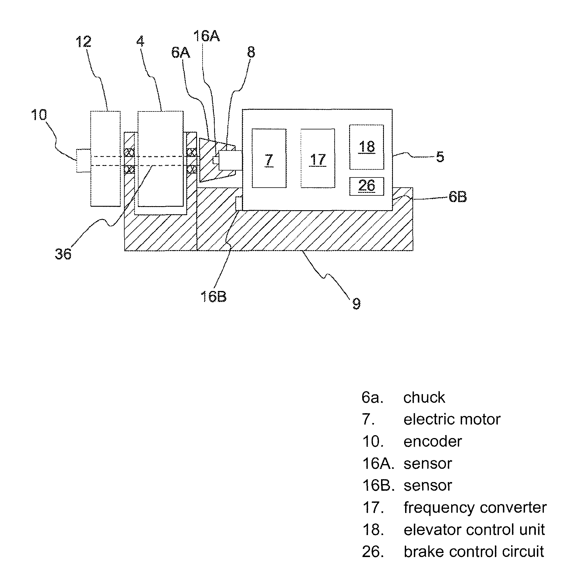
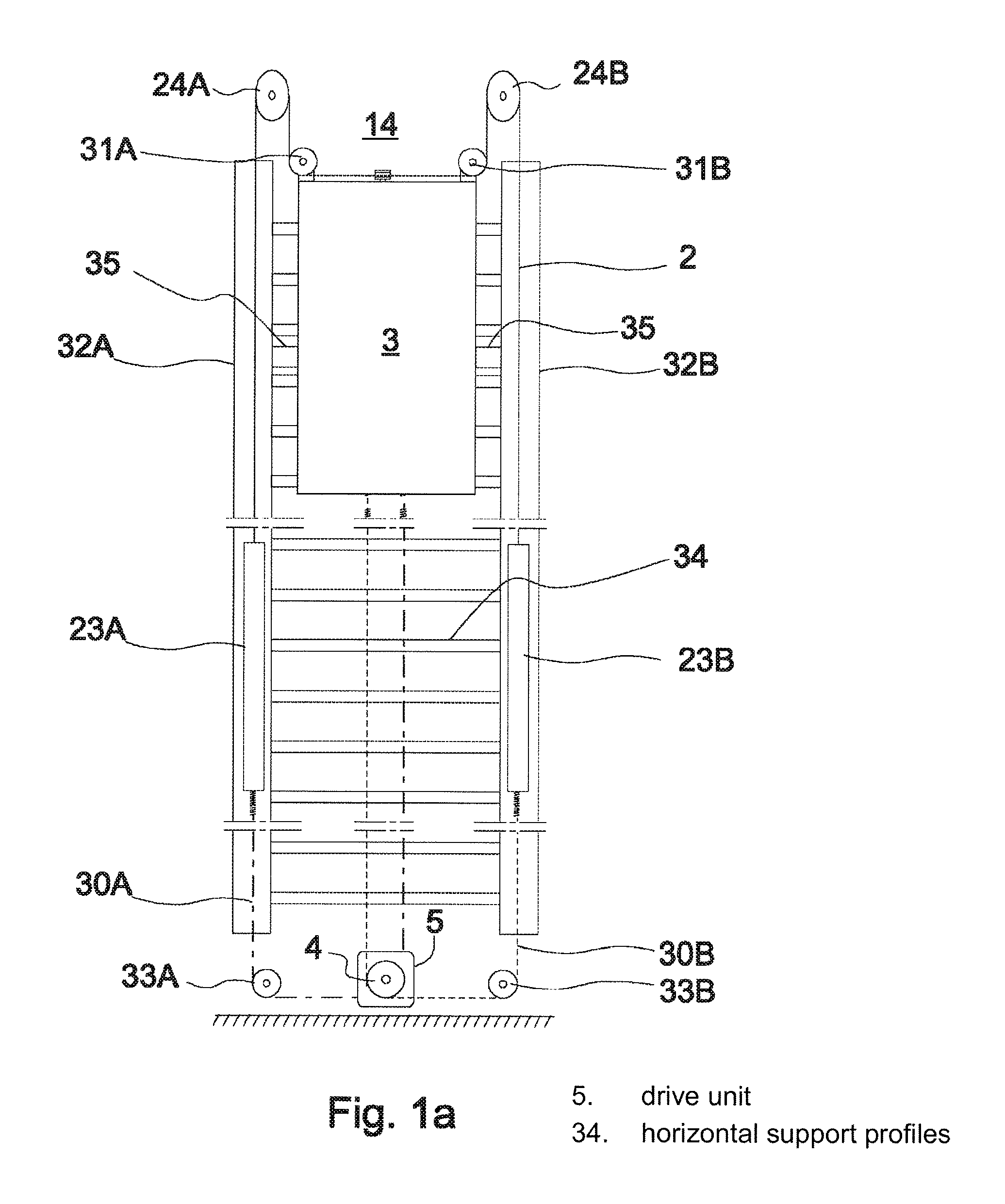
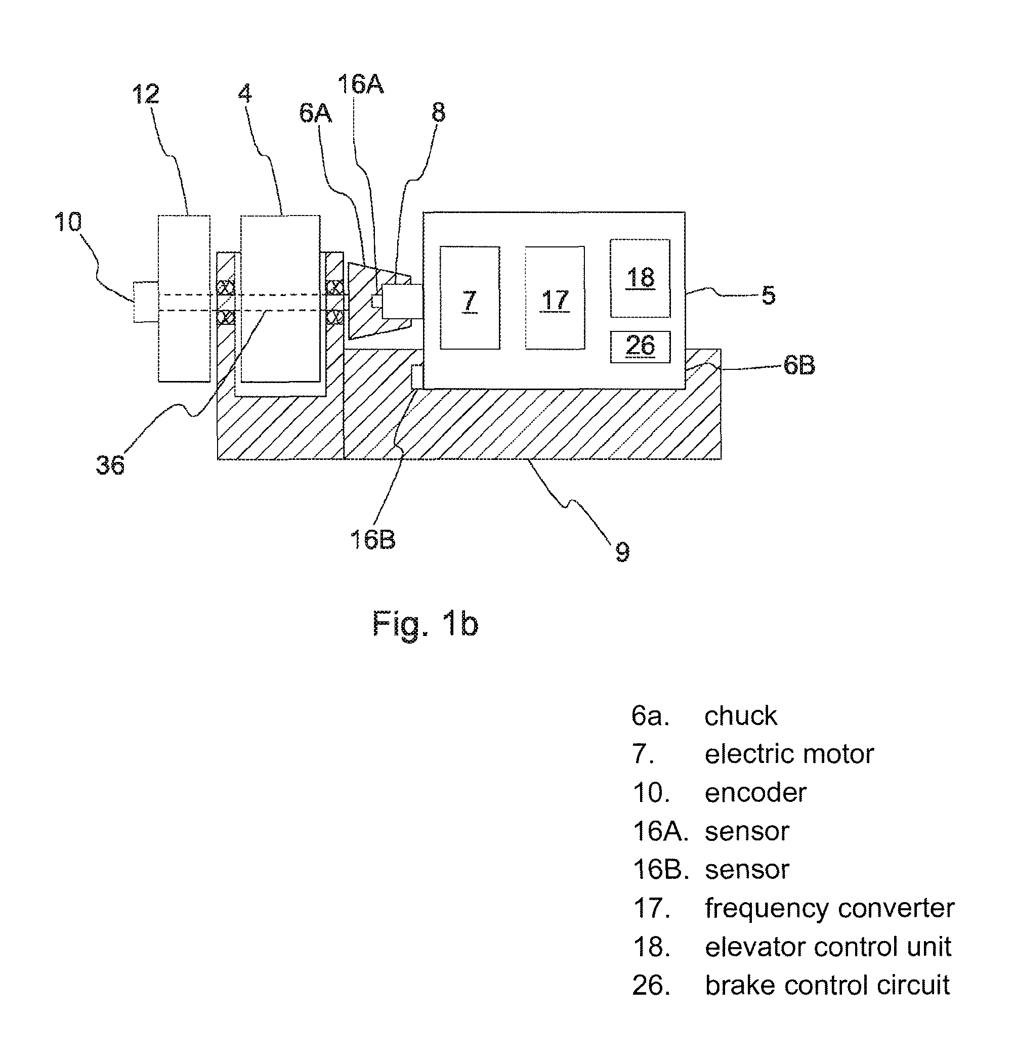
[0062]The elevator presented in FIG. 1a can function e.g. as a service elevator of a wind power station 13 according to FIG. 4. The elevator car 3 in FIG. 1 is suspended in the elevator car 14 on a cable 2, which travels from diverting pulleys 31A, 31B fixed in a manner allowing rotation to the top part of the elevator car 3 via diverting pulleys 24A, 24B fixed in a manner allowing rotation to a supporting structure in the top part of the elevator tower 14 downwards by the sides of the elevator car 3 along parallel hollow profiles 32A, 32B and are fixed to compensating weights 23A, 23B, which also travel in the aforementioned hollow profiles 32A, 32B. Fixed to the compensating weights 23A, 23B are also belts 30A, 30B, which travel in the same hollow profiles 32A, 32B downwards from the compensating weights 23A, 23B via diverting pulleys 33A, 33B fixed in a manner allowing rotation to a supporting structure of the bottom end zone of the elevator tower to the traction grooves of the t...

embodiment 2

[0070]The elevator 1 of FIG. 2 differs from the elevator presented in FIG. 1a in that the elevator car 3 is suspended on a cable 2 in the elevator 14, which cable travels downwards from the elevator car 3 via a diverting pulley 24 in the top part of the elevator tower 14 to a drum collecting, distributing cable 2 as it rotates, said drum being in the bottom end zone of the elevator tower 14. The elevator car 3 moves when the drum 4 is rotated with a drive unit 5 temporarily fixed to the drum 4. In addition, in connection with the drum 4 are one or more controllable machinery brakes 12, which when activated engage mechanically with the braking surface of the drum / drum shaft to brake the movement of the drum 4. The elevator car is controlled with a separate control cable 41, to which the elevator car 3 is connected with a controller 40.

[0071]The drive unit 5 is in its basic principles according to embodiment 1, comprising the same functional parts; also the fixing of the shaft of the ...

embodiment 3

[0072]The elevator 1 of FIG. 3 differs from the elevators of FIGS. 1a and 2 in that a detachable drive unit 5 is fixed to a traction sheave 4 supported on the roof of the elevator car 3 in a manner allowing rotation, in connection with the traction sheave 4 via a reduction gear (not in figure). The elevator car 3 is suspended on a cable 2 by circulating the cable 2 once around a traction sheave 4. The cable 2 running in a vertical direction in the elevator tower 14 is fixed in position at its top end and at its bottom end on a supporting structure of the elevator tower 14. The drive unit 5 is in its basic principles according to embodiments 1 or 2, comprising the same functional parts; also the fixing of the shaft 8 of the electric motor in the drive unit 5 onto a rotating traction sheave 4 is of the same type as the fixing between the shaft 8 and the traction sheave / drum 4 in embodiments 1 or 2. The drive unit 5 is also fixed to a supporting structure of the roof of the elevator ca...


PUM


Abstract

An elevator including one or more hoisting members that are continuous in the vertical direction, a load-receiving part suspended on the hoisting member, and also a driving member engaging with the hoisting member for moving the load-receiving part. The driving member engaging with the hoisting member is configured to be driven with a detachable drive unit.

Description

[0001]This application is a Continuation of PCT / FI2012 / 050783 filed on Aug. 13, 2012, which claims priority under 35 U.S.C. 119(a) to Patent Application No. 20115827 filed in Finland on Aug. 26, 2011, all which are hereby expressly incorporated by reference into the present application.FIELD OF THE INVENTION[0002]The invention relates to elevators, more particularly to methods for connecting and operating the drive units of elevators.BACKGROUND OF THE INVENTION[0003]The servicing work, installation work and repair work of an object to be serviced, such as a wind power station, an oil drilling platform, a lighthouse, et cetera, usually requires that the object comprises an elevator, with which it is possible to move and to lift a load in the vertical direction. The structure of this type of elevator can vary, but the elevator usually comprises an elevator car, a lifting platform or corresponding load-receiving part, with which a load is transferred. The load-receiving part is suspend...

Claims


Application Information

Patent Timeline
Patent Type & Authority Patents(United States)
IPC IPC(8): B66B7/00B66B9/00B66B11/04E04H12/00B66B9/187
CPCB66B11/04B66B9/00B66B9/187E04H12/00F03D13/20F03D80/00Y02E10/722Y02E10/728F03D13/40F03D80/50Y02E10/72B66B1/00H02K7/10H02K7/14
Inventor TALONEN, TAPANI
Owner KONE CORP
Learn More