
Purification arrangements and methods for gas pipeline systems

a technology of purification arrangements and gas pipelines, applied in separation processes, transportation and packaging, dispersed particle separation, etc., can solve the problems of still being laden with particulates, affecting the components of the pipeline system and the personnel, and affecting the safety of personnel, etc., to achieve the effect of high removal efficiency, quick and easy removal and installation, and high removal efficiency

Active Publication Date: 2014-05-15
PALL CORP
View PDF6 Cites 9 Cited by
  • Summary
  • Abstract
  • Description
  • Claims
  • Application Information

AI Technical Summary

Benefits of technology

The purification arrangements and methods described in this patent have several beneficial features. First, they effectively remove particulate matter from the gas, especially black powder. Second, they are easy to install and remove from a horizontal pressure vessel. Third, they are modular in design, meaning they can be easily replaced or restructured to accommodate varying gas flow conditions without modifying the pressure vessel. These features significantly improve the efficiency and flexibility of the purification process.

Problems solved by technology

For example, gas entering the pipeline system from a gas treatment facility after it has been extracted from a well may still be laden with particulates.
Many of these particulates are harmful to the components of the pipeline system and the personnel who operate and service the pipeline system.

Method used


Image

  • Purification arrangements and methods for gas pipeline systems
  • Purification arrangements and methods for gas pipeline systems
  • Purification arrangements and methods for gas pipeline systems

Examples


Embodiment Construction

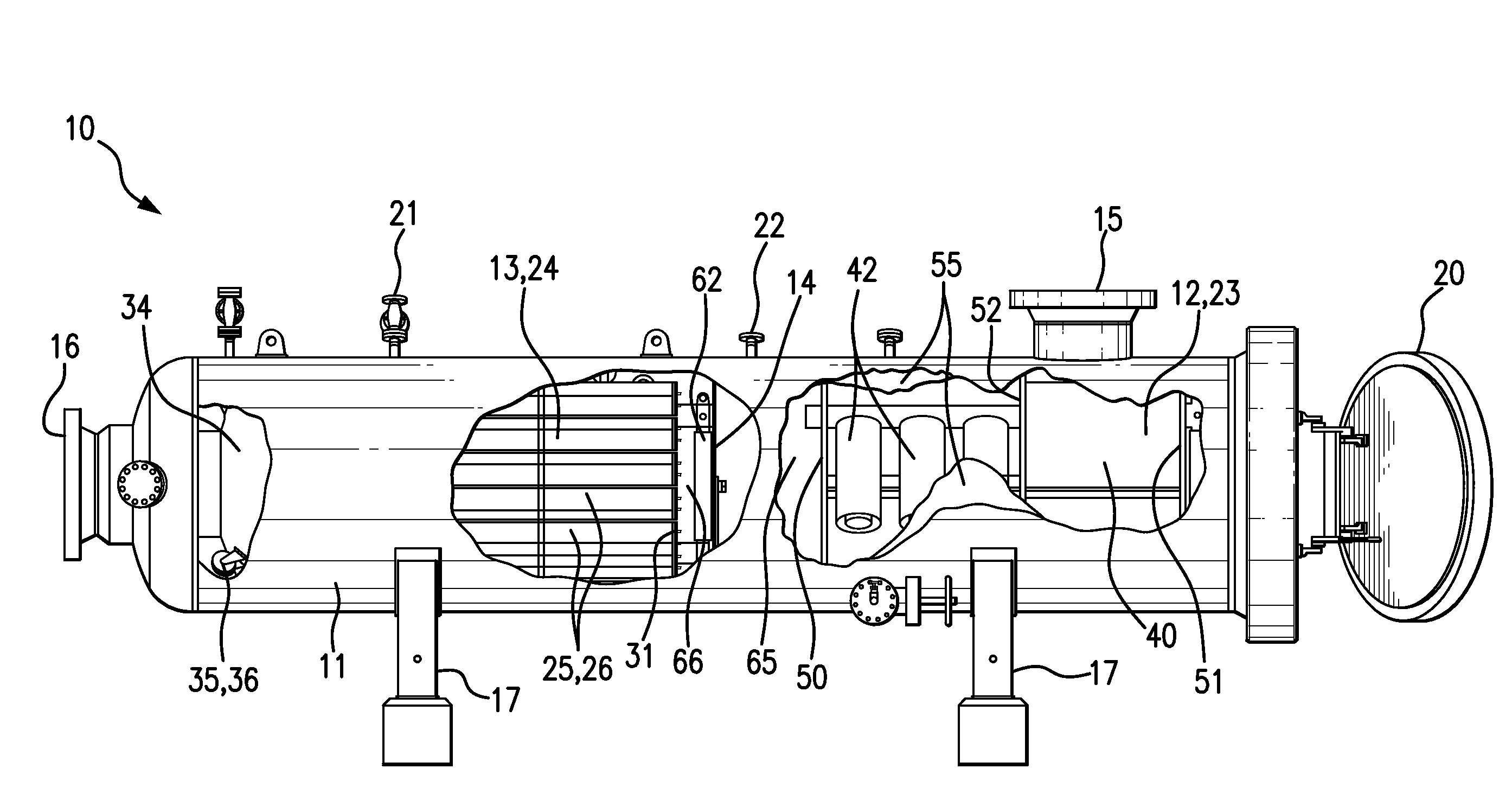
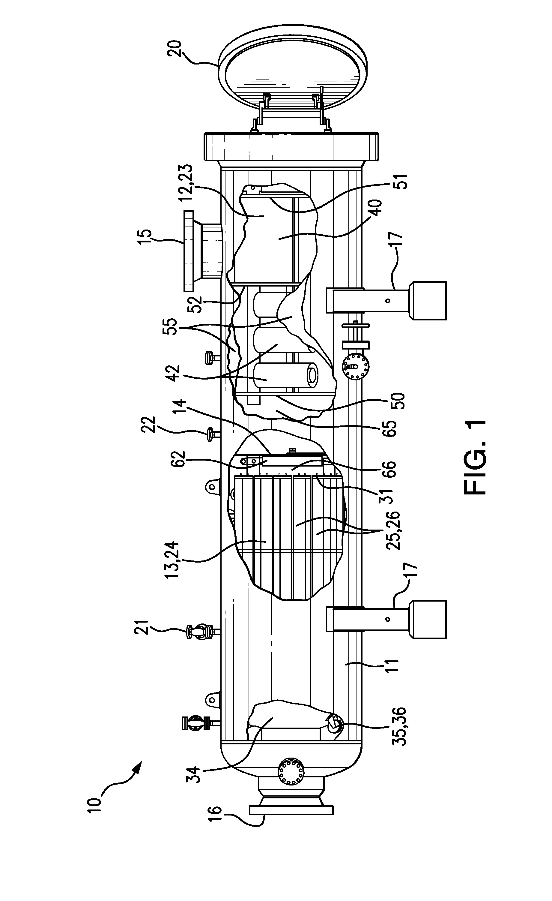
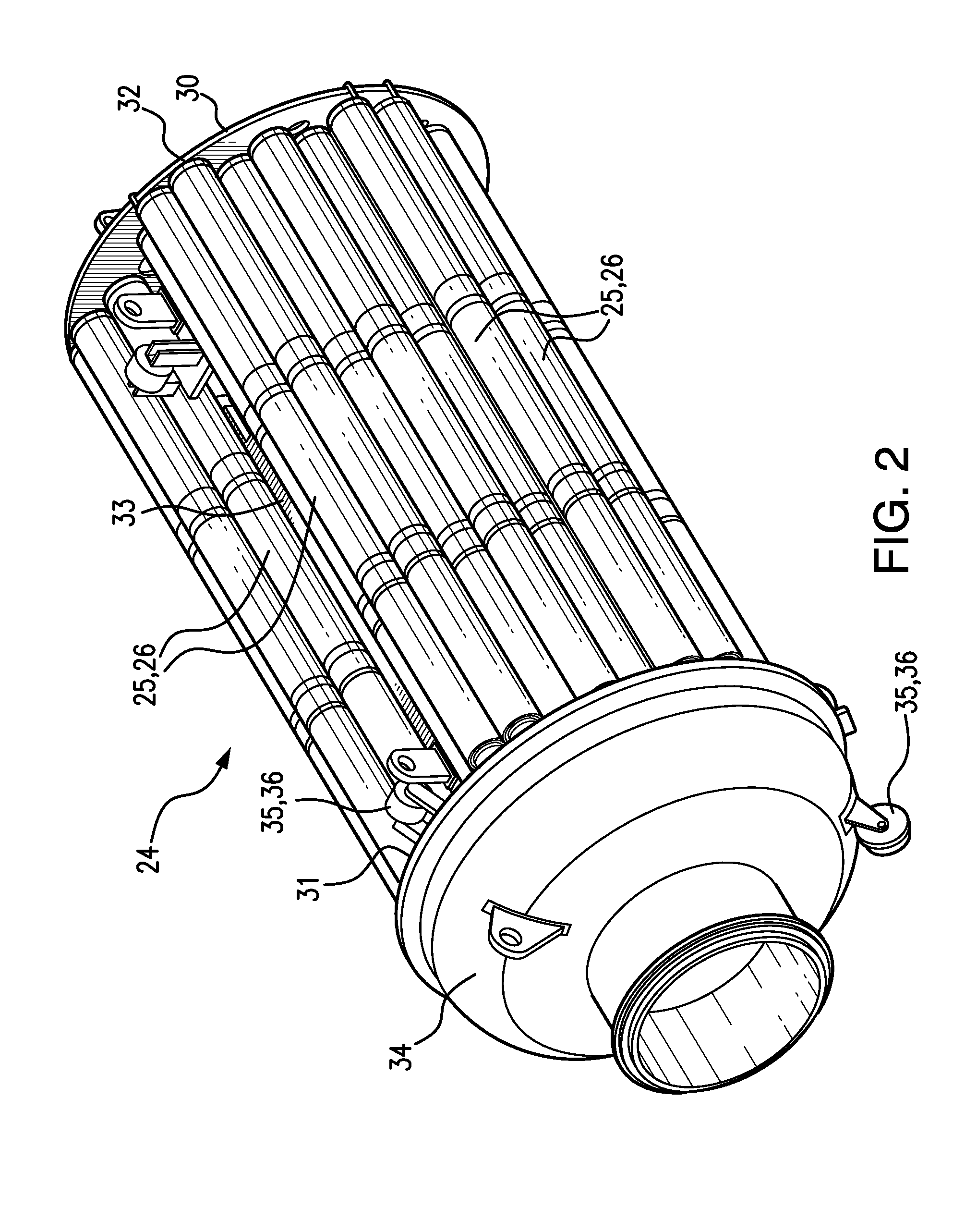
[0012]Purification arrangements embodying the invention may be configured in a wide variety of different ways. For example, the purification arrangement 10 shown in FIG. 1 may comprise a pressure vessel 11 and two or more purification assemblies 12, 13 located in the interior of the pressure vessel 11. The pressure vessel 11 may have a gas inlet 15 and a gas outlet 16 coupled to a gas pipeline system (not shown) and may define a gas flow path through the interior of the pressure vessel between the gas inlet 15 and the gas outlet 16. The purification assemblies 12, 13, one a modular separator assembly and the other a modular filter assembly, may be positioned in the gas flow path between the gas inlet 15 and the gas outlet 16. Natural gas or any other gas passing through the gas pipeline system is directed through the pressure vessel 11 from the gas inlet 15 through the purification assemblies 12, 13 to the gas outlet 16. A significant portion of the particulates, e.g., almost all so...


PUM

PropertyMeasurementUnit
temperatureaaaaaaaaaa
sizeaaaaaaaaaa

Abstract

A purification arrangement for a gas pipeline system includes a pressure vessel and at least a modular separator assembly and a modular filter assembly in the interior of the pressure vessel. A gas flow may be established through the pressure vessel, and the gas may pass through the modular separator and filter assemblies to remove liquid and / or solid particulates from the gas.

Description

DISCLOSURE OF THE INVENTION[0001]Natural gas and other gases transmitted through pipeline systems may carry many types of particulates, including liquid droplets and / or solid particles. The gas may be the source of the particulates. For example, gas entering the pipeline system from a gas treatment facility after it has been extracted from a well may still be laden with particulates. Or the particulates may be generated within the pipeline system itself. For example, solid particles may be generated by corrosion and abrasion within the pipeline system. Liquid droplets may arise from condensation or as residues of liquid cleaners for the pipeline system. Many of these particulates are harmful to the components of the pipeline system and the personnel who operate and service the pipeline system. For example, the gas may carry black powder, a general term used to describe a host corrosion-related particulate contaminants, that can be erosive, toxic, and / or chemically reactive with air,...

Claims


Application Information

Patent Timeline
Patent Type & Authority Applications(United States)
IPC IPC(8): B01D46/00
CPCB01D46/0027B01D45/12B01D46/0012B01D46/0091B01D46/2407B01D46/90B01D50/20
Inventor CABOURDIN, JEAN-PIERRETRIFILIEFF, OLIVIERBLANC, PIERRESAMAHA, JOSEPH
Owner PALL CORP
Learn More