RFID tag

a technology of rfid tags and rfid tags, which is applied in the field of rfid tags, can solve the problems of low transmitting power of rfid tags mounted in this manner on instruments, and the inability to handle simple everyday hospital routines, and achieves stable anchoring of tags, good cleanability, and high flexibility.

Active Publication Date: 2014-05-15
AESCULAP AG
View PDF9 Cites 20 Cited by
  • Summary
  • Abstract
  • Description
  • Claims
  • Application Information

AI Technical Summary

Benefits of technology

[0012]In addition to stable anchoring of the tag on the instrument, the RFID tags according to the invention enable secure encapsulation, good cleanability, as well as a positioning of the RFID element in the housing which allows unhindered emission from the RFID element.
[0013]Furthermore, a high level of flexibility is provided in terms of the selection of the location on the instrument where the RFID tag is to be positioned.
[0014]The housing including its accommodating chamber can be implemented as a simple encapsulation, the RFID element being moulded into the housing material. A separate production step for forming the accommodating chamber is not necessary in this embodiment.

Problems solved by technology

The two known solutions have the problem that the transmitting power of the RFID element of the RFID tag is comparatively low.
Nevertheless, the transmitting power of RFID tags mounted in this manner on instruments is still too low for simple handling in everyday hospital routines.

Method used


Image

  • RFID tag
  • RFID tag
  • RFID tag

Examples


first embodiment

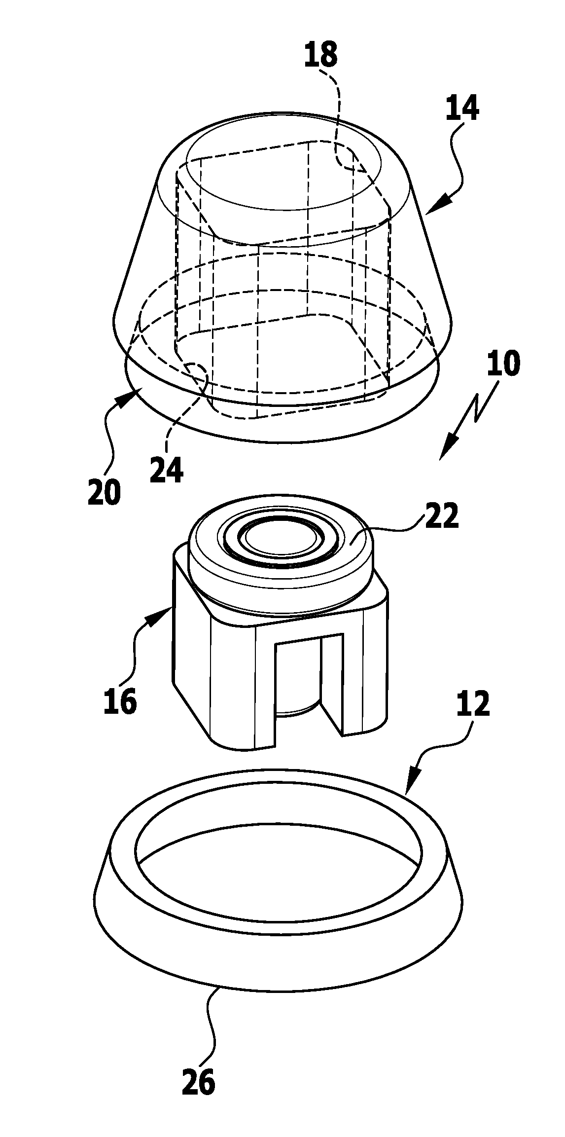
[0036]FIG. 1A shows an exploded view of an RFID tag according to the invention;

[0037]FIG. 1B shows a sectional drawing of the assembled RFID tag of the first embodiment in FIG. 1A;

second embodiment

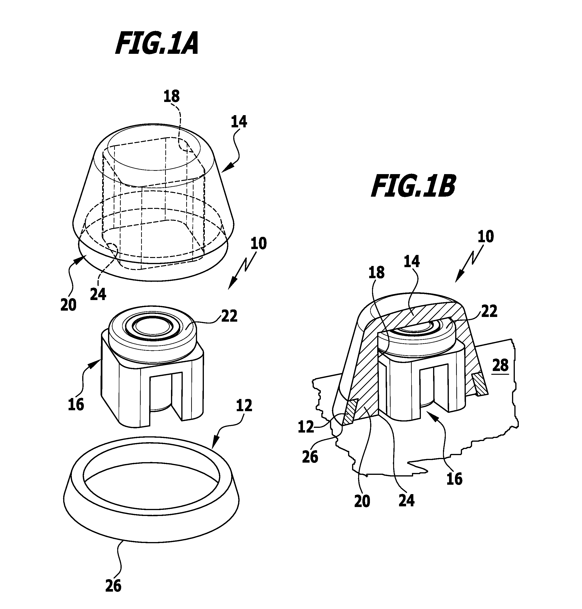
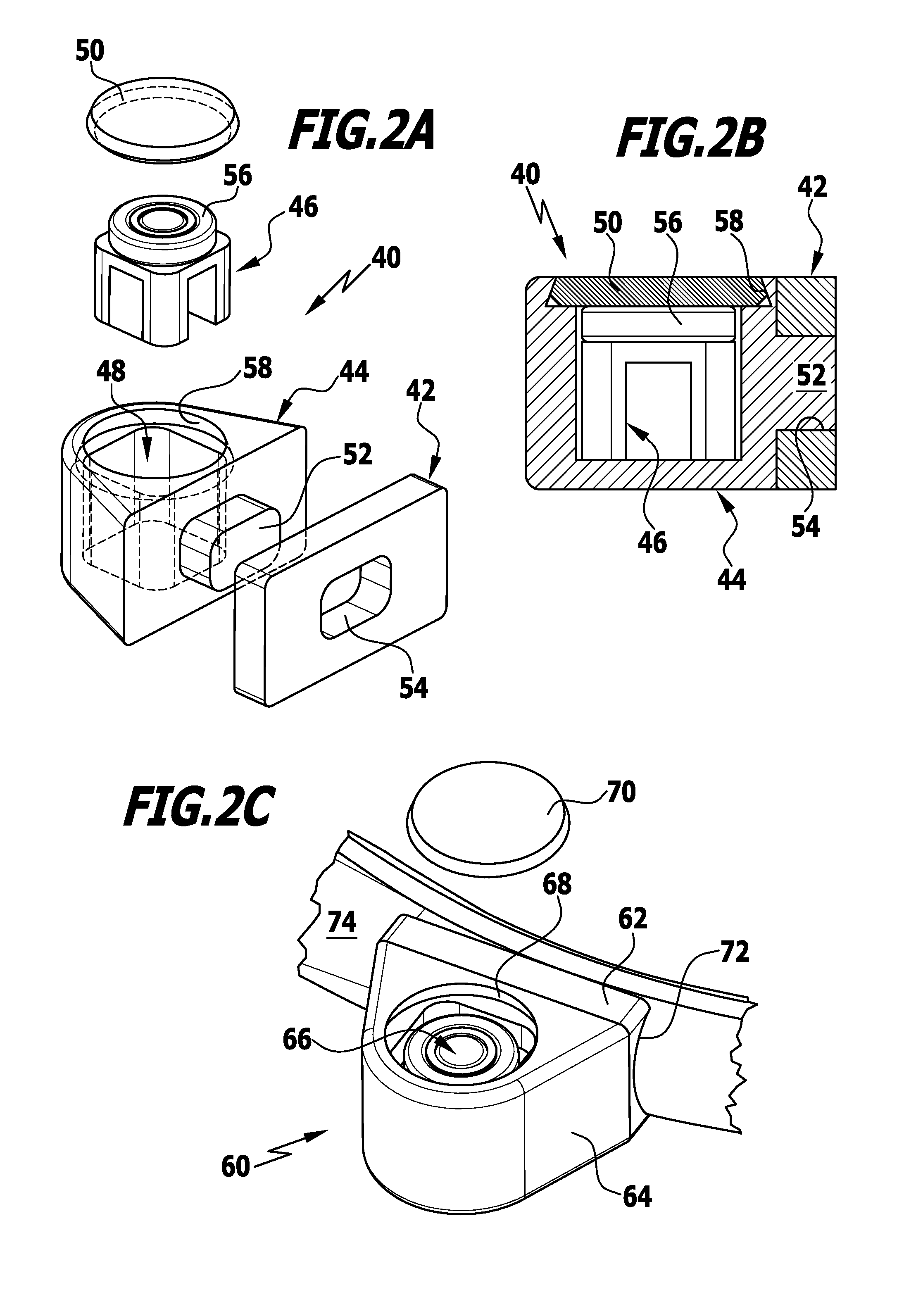
[0038]FIG. 2A shows an exploded view of the RFID tag according to the invention;

[0039]FIG. 2B shows a sectional drawing of the assembled RFID tag in FIG. 2A;

[0040]FIG. 2C shows the RFID tag in FIG. 2A, held on a surgical instrument;

third embodiment

[0041]FIG. 3A shows an exploded view of an RFID tag according to the invention;

[0042]FIG. 3B shows a sectional view of the assembled RFID tag in FIG. 3A;

[0043]FIG. 4 shows a surgical instrument having an RFID tag according to the invention as shown in FIG. 1A;

[0044]FIG. 5 shows a further surgical instrument having an RFID tag according to the invention as shown in FIG. 1A;

[0045]FIG. 6 shows a further surgical instrument having an RFID tag according to the invention as shown in FIG. 1A;

[0046]FIG. 7 shows a further surgical instrument having two RFID tags according to the invention as shown in FIGS. 1A and 2C;

[0047]FIG. 8 shows a further surgical instrument having two RFID tags according to FIG. 1A mounted thereon; and

[0048]FIG. 9 shows a further surgical instrument having an RFID tag according to FIG. 3A mounted thereon.


PUM


Abstract

An RFID tag is provided that is suitable for mounting on surgical instruments, and by means of which stable anchoring on the instrument, encapsulation of the RFID elements from the surroundings, good cleanability and improved detectability can be achieved. The RFID tag has a metal holder, a housing that is made of an electrically non-conductive or slightly conductive material, an accommodating chamber and an RFID element with an antenna. The RFID element is arranged in the accommodating chamber of the housing. The housing has a first end which is held on the metal holder. The accommodating chamber in the housing is formed to be spatially spaced apart from the first end of the housing. The RFID element is positioned in the accommodating chamber in such a way that the antenna of the RFID element is spatially arranged substantially outside of the metal holder.

Description

[0001]This application is a continuation of international application number PCT / EP2012 / 065324 filed on Aug. 6, 2012 and claims the benefit of German application number 10 2011 052 501.7 filed on Aug. 8, 2011, which are incorporated herein by reference in their entirety and for all purposes.BACKGROUND OF THE INVENTION[0002]The invention relates to an RFID marking element for mounting on surgical instruments, hereinafter referred to as “tag” for short.[0003]Conventional RFID tags for mounting on surgical instruments comprise, in addition to a substantially annular metal holder, a disc-shaped plastics or ceramic body that is surrounded by the metal holder. The metal holder itself can be secured by welding, in particular laser welding, to an instrument on which a tag is to be mounted.[0004]In other solutions, an RFID element is potted in a hole in the instrument.[0005]The advantages of surgical instruments on which RFID tags are mounted are their easy identifiability and traceability, ...

Claims


Application Information

Patent Timeline
Patent Type & Authority Applications(United States)
IPC IPC(8): G06K19/077
CPCG06K19/07758A61B17/2812A61B17/3201A61B17/3211G06K19/07771A61B90/90A61B90/98
Inventor WEISSHAUPT, DIETERMORALES, PEDRO
Owner AESCULAP AG
Why Eureka
Try Eureka