Double-curved cover for covering a gap between two structural portions of an aircraft

a technology for aircraft and structural parts, applied in aircraft accessories, aircraft lighting protectors, aircraft indicators, etc., can solve the problem that the plain prior art cover does not provide a close fit onto the double-curved skin, and achieve the effect of simple and cost-effectiv

Inactive Publication Date: 2014-05-15
SAAB AB
View PDF16 Cites 5 Cited by
  • Summary
  • Abstract
  • Description
  • Claims
  • Application Information

AI Technical Summary

Benefits of technology

[0029]In such way it is quite simple and cost efficient to remove a defect or worn out cover from the structural portion and replace it. Preferably, the f...

Problems solved by technology

A plain prior art cover would not pro...

Method used


Image

  • Double-curved cover for covering a gap between two structural portions of an aircraft
  • Double-curved cover for covering a gap between two structural portions of an aircraft
  • Double-curved cover for covering a gap between two structural portions of an aircraft

Examples


first embodiment

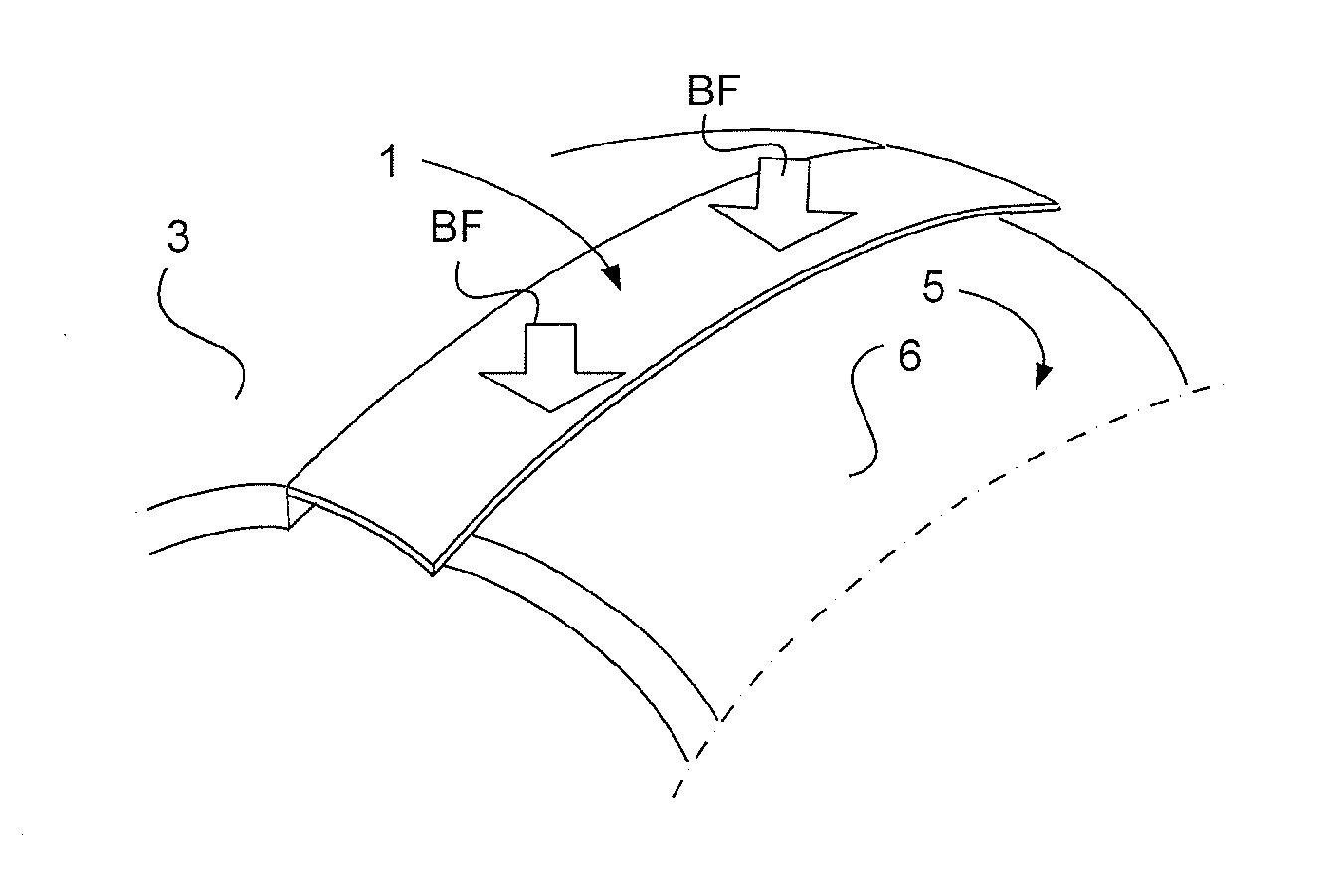
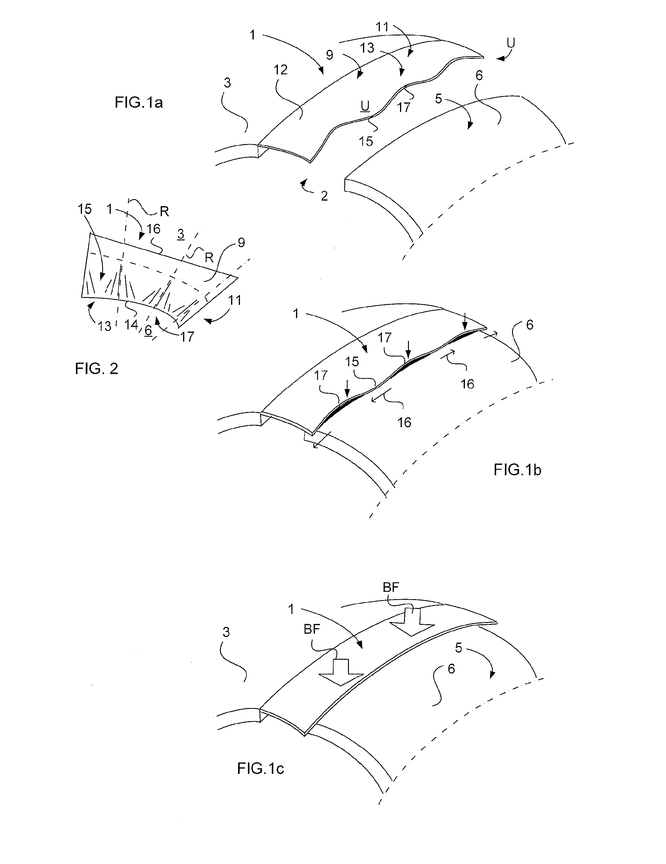
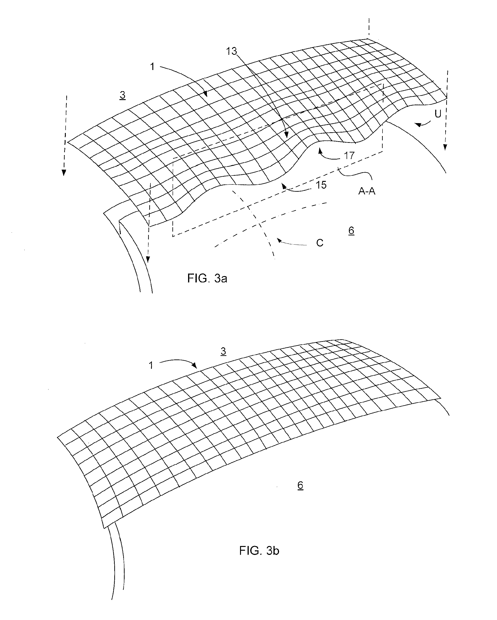
[0041]FIGS. 1a-1c schematically show a cover 1 illustrating the principle of achieving a close fit between the cover 1 and a double-curved surface. FIG. 1a illustrates the cover 1 for covering a gap 2 between a wing skin 3 and a skin 5 of a movable elevator of an aircraft (not shown). The both skins and the cover 1 are made of fibre reinforced resin. The cover 1 includes a first attachment section 9 which can be fasten to the wing skin 3 by means of glue. The cover 1 further includes a flexible section 11 which is adapted to cover the gap 2. An abutment portion 13 of the flexible section 11 is adapted to abut against the skin 5 of the movable elevator when the aircraft operates. The abutment portion 13 forms in an unloaded state (FIG. 1a) an undulating shape U. The undulating shape U presents troughs 15 and crests 17, which extend along a double curved plane. This double curved plane has a curvature corresponding essentially with the curvature of the skin's 5 outer surface 6 within ...

second embodiment

[0042]FIG. 2 illustrates a cover 1. A portion of the flexible section 11 forms an undulating shape in the unloaded state, includes wave ridges R that are arranged in a fan-shaped manner. In such way it is achieved that the first attachment section 9 can be fasten smoothly to a plain surface of the first structural portion, such as a wing skin 3. In an unloaded state, the abutment portion 13 of the cover 1 forms a single-curved plane. The wave ridges R are straight. The longitudinal edge 14 of the cover's 1 abutment portion 13, which edge 14 is the main edge meeting the outer surface 6 of the skin 5 of the movable elevator, will have the same length as the edge 16 of the attachment section 9 parallel with the edge 14. However, due to the undulating shape, the cover 1 being illustrated from above will be projected as it comprises a longer edge 16 of the attachment section 9 than the edge 14. The wave ridges R of the crests 17 and troughs 15 have such orientation within the cover 1 tha...

fourth embodiment

[0046]FIGS. 6a-6b illustrate a cover 1 in the shape of a double-curved hatch or access panel 25. According to this embodiment the first attachment section 9 of the hatch also includes an abutment portion 13a comprising an undulating shape U. The hatch 25 is made of a composite laminate sheet 26 including electrically conductive material. The hatch 25 is mountable to a fuselage skin 27 of a helicopter 29, shown in FIG. 9. The skin 27 of the helicopter has an electrically conductive property as well. Thereby is achieved that detection of the gap 2 by radar is hard to reach. This is due to the eliminating of the radar echo otherwise produced by the gap 2 between the fuselage skin 27 and a prior art hatch. The electrical conductivity of the hatch 25 connects the first and second structural portions 3′, 5′ of the fuselage skin 27 on opposite sides of the gap 2, thus decreasing the electrical discontinuities between the both structural portions 3′, 5′ and achieving the helicopter 29 less ...


PUM


Abstract

A cover for covering a gap between a first structural portion and a second structural portion of an aerial vehicle. A first attachment section is attachable to the first structural portion. A second flexible section covers the gap. The second flexible section includes an abutment portion for abutting against the second structural portion in an operating state. The abutment portion in an unloaded state forms an undulating shape having troughs and crests extending along a curved plane. The curvature of the curved plane essentially corresponds with the curvature of the surface of the second structural portion. The troughs are provided for engagement with the surface in the operating state such that the troughs tend to be flatten out and propagate over the surface pressing down neighboring crests towards the surface for providing a close fit between the cover and the second structural portion.

Description

TECHNICAL FIELD[0001]The present invention relates to a cover for covering a gap between a first structural portion and a second structural portion of an aerial vehicle, according to the preamble of claim 1.BACKGROUND ART[0002]An aerial vehicle during flight generates radar echoes to a radar sensing threats who try to detect the vehicle. Such source for generating a radar echo could be a gap between a wing and the vehicle's movable control surface, such as an aileron surface, or a gap between the fuselage skin and a service hatch, etc. The aerial vehicle could be a military aircraft, a helicopter, an unmanned aerial vehicle, a missile etc. The modern aerial vehicle includes often double-curved outer surfaces or aerodynamic surfaces.[0003]Efforts have been made for decreasing the detectability of such gaps by radar. U.S. Pat. No. 5,695,154 describes a gap filler including a horizontal portion extending across the gap and vertical portions biased into frictional engagement with side w...

Claims


Application Information

Patent Timeline
IPC IPC(8): B64D45/02B64C7/00
CPCB64C7/00B64C1/14B64D45/02B64C2025/003
Inventor BJERKEMO, JAKOB
Owner SAAB AB
Why Eureka
Try Eureka