Check patentability & draft patents in minutes with Patsnap Eureka AI!

Ophthalmic imaging apparatus, control method for ophthalmic imaging apparatus, and storage medium

a technology control method, which is applied in the field of ophthalmic imaging apparatus, can solve the problems of deterioration in the operability of the ophthalmic imaging apparatus having the automatic imaging function, impose burden on an object, etc., and achieve the effect of reducing the operation burden on the operator and increasing the burden on an obj

Inactive Publication Date: 2014-05-15
CANON KK
View PDF1 Cites 1 Cited by
  • Summary
  • Abstract
  • Description
  • Claims
  • Application Information

AI Technical Summary

Benefits of technology

The present invention is an ophthalmic imaging machine that can automatically adjust the brightness of the imaging light and take a photo when the machine is ready. This makes it easier to capture photos without causing discomfort to the patient and reducing the workload for the operator. Overall, the invention improves the efficiency and comfort of ophthalmic imaging procedures.

Problems solved by technology

In addition, as disclosed in Japanese Patent Laid-Open No. 2005-279154, the ophthalmic imaging apparatus configured to execute actual imaging upon causing the imaging light source to emit test light may impose burden on an object due to test light emission.
This may lead to a deterioration in the operability of the ophthalmic imaging apparatus having the automatic imaging function.

Method used


Image

  • Ophthalmic imaging apparatus, control method for ophthalmic imaging apparatus, and storage medium
  • Ophthalmic imaging apparatus, control method for ophthalmic imaging apparatus, and storage medium
  • Ophthalmic imaging apparatus, control method for ophthalmic imaging apparatus, and storage medium

Examples


first embodiment

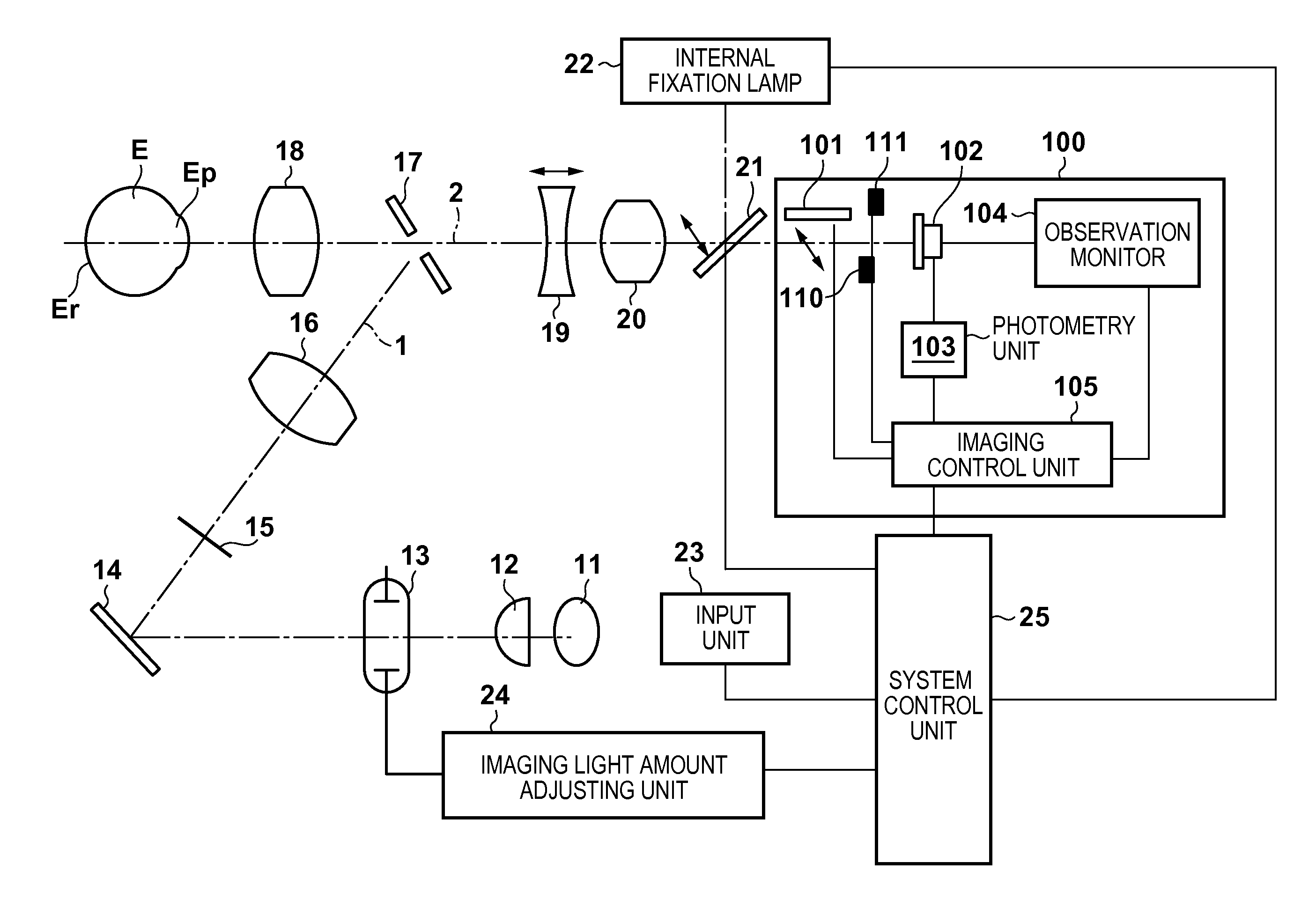
[0018]FIG. 1 is a view showing the arrangement of an ophthalmic imaging apparatus according to the first embodiment of the present invention. This embodiment will exemplify the arrangement of a non-mydriatic ophthalmic imaging apparatus as an ophthalmic imaging apparatus. A condenser lens 12, an imaging light source 13, a mirror 14, a stop 15 having a ring-like aperture, a relay lens 16, and a perforated mirror 17 are sequentially arranged on an optical path extending from an observation light source 11 to an objective lens 18 to constitute a fundus illumination optical system 1. A focusing lens 19, an imaging lens 20, and a flip-up mirror 21 are arranged on an optical path in the transmitting direction of the perforated mirror 17 to constitute a fundus imaging optical system 2 extending to an image sensor 102 placed in an imaging unit 100. An internal fixation lamp 22 including aligned / arranged light-emitting members such as LEDs for guiding the fixation of an eye E to be examined ...

second embodiment

[0035]An ophthalmic imaging apparatus according to the second embodiment of the present invention will be described with reference to FIGS. 4 and 5. FIG. 4 is a block diagram for explaining the functional arrangement of the ophthalmic imaging apparatus according to the second embodiment. FIG. 5 is a flowchart for explaining a procedure for automatic imaging control in the ophthalmic imaging apparatus. As shown in FIG. 4, the ophthalmic imaging apparatus according to the second embodiment additionally includes an observation light amount adjusting unit 28 for adjusting the light amount of the observation light source 11. The same reference numerals as in the first embodiment denote the same constituent elements of the functional arrangement in FIG. 3B.

[0036]First of all, an alignment unit 30 performs rough alignment between the ophthalmic imaging apparatus and an eye E to be examined during the observation of the anterior eye segment of the eye E (anterior eye segment observation mod...


PUM


Abstract

An ophthalmic imaging apparatus including an observation light source configured to emit observation light for observation of an eye to be examined and an imaging light source configured to emit imaging light for imaging the eye, the apparatus comprises a photometry unit configured to acquire a photometric value of an observation image of the eye illuminated by the observation light source; an alignment processing unit configured to perform alignment processing to match the eye with a target position; an imaging light amount adjusting unit configured to adjust a light amount of the imaging light source by using the photometric value before completion of the alignment processing; and an imaging processing unit configured to image the eye by using a light amount adjusted by the imaging light amount adjusting unit after completion of the alignment processing.

Description

BACKGROUND OF THE INVENTION[0001]1. Field of the Invention[0002]The present invention relates to an ophthalmic imaging apparatus, a control method for the ophthalmic imaging apparatus, and a storage medium.[0003]2. Description of the Related Art[0004]Some ophthalmic imaging apparatuses designed to image the fundus of an eye to be examined have an automatic imaging function of automatically performing imaging operation to reduce the operation burden on an operator when determining that the alignment state and in-focus state of the ophthalmic imaging apparatus are proper. Some other ophthalmic imaging apparatuses have an imaging light amount automatic adjustment function of automatically setting the imaging light amount of an imaging light source.[0005]For example, Japanese Patent Laid-Open No. 2009-172154 discloses an ophthalmic imaging apparatus which automatically performs imaging operation when determining that check results on an alignment state and an in-focus state fall within ...

Claims


Application Information

Patent Timeline
IPC IPC(8): A61B3/15
CPCA61B3/152
Inventor KAWASE, DAISUKESAGANO, OSAMU
Owner CANON KK
Features
  • R&D
  • Intellectual Property
  • Life Sciences
  • Materials
  • Tech Scout
  • Unparalleled Data Quality
  • Higher Quality Content
  • 60% Fewer Hallucinations
Learn More