Wireless communications system and method

a communication system and wireless technology, applied in the field of wireless communications system and method, can solve the problems of increased latency, increased side effects, and increased

Active Publication Date: 2014-05-15
CONVIDA WIRELESS LLC
View PDF5 Cites 11 Cited by
  • Summary
  • Abstract
  • Description
  • Claims
  • Application Information

AI Technical Summary

Benefits of technology

[0030]In this way, the various devices within the network are able to discover neighbouring devices and the quality of radio links with those neighbouring devices. The base station is able to receive all of this information to determine a suitable route through the network for uplink data. It will be appreciated that it may not be necessary for all devices to transmit beacon signals, particularly where certain radio links are fixed geographically.

Problems solved by technology

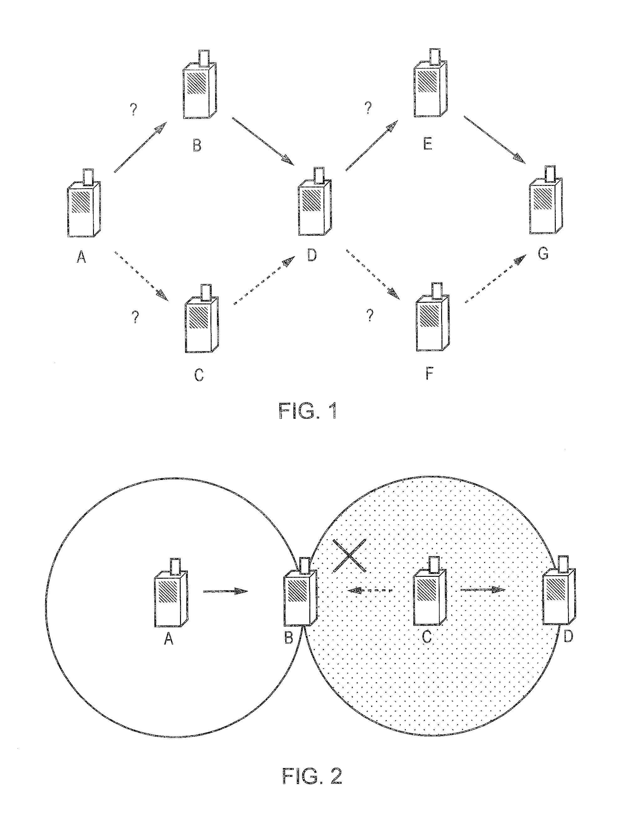
However, in order to reliably convey information from a source to a destination, this topology encounters several problems.
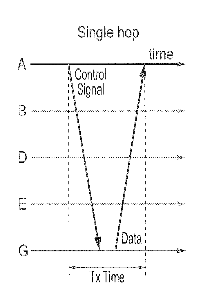
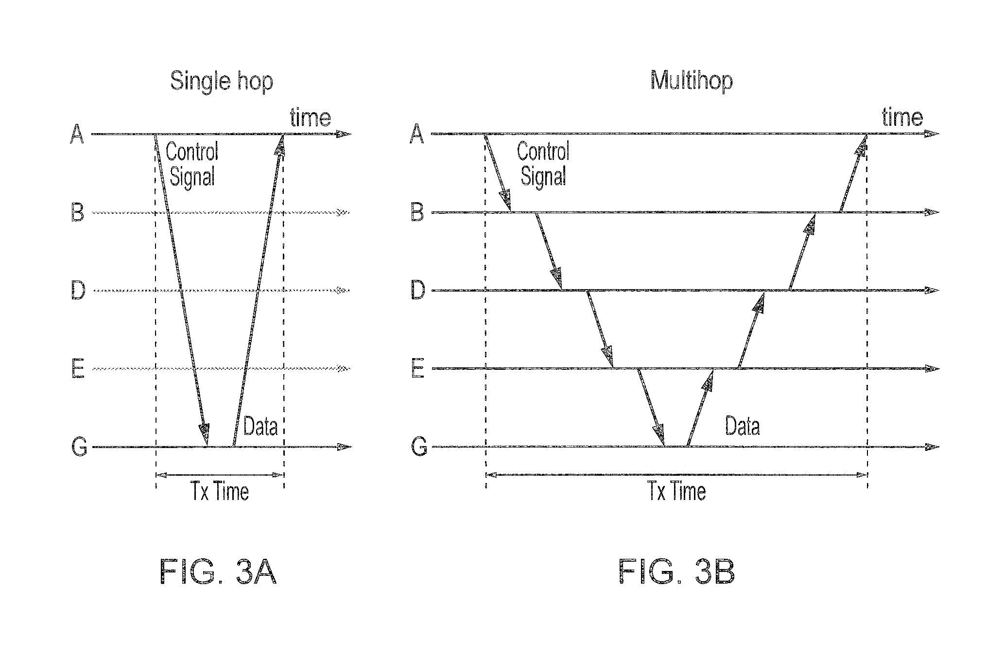
As can be understood from a comparison of FIGS. 3A and 3B, not only does multi-hopping increase the latency to transfer information from source to destination, but it also has some additional side effects.
Routing signals and traffic flow control signals may also be sent multiple times, making the effect more serious.
This problem is particularly significant in MTC where there may be large numbers of terminals, and for which the signalling information (control signals) is likely to dominate the actual information (data) transmitted.
These same problems (excessive use of medium) can be observed in a Relay topology or when a gateway is used.
However, it will also be understood from the above discussion that Relay and Mesh topologies have their own drawbacks in that each relay or mesh terminal needs to have distributed scheduling and routing capability in order to convey information in a multihop manner, which brings complexity to these terminals.
Furthermore, the scheduling messages need also to be multihopped, which results in an ineffective use of the medium.
This creates some problems.

Method used


Image

  • Wireless communications system and method
  • Wireless communications system and method
  • Wireless communications system and method

Examples


Embodiment Construction

[0089]Referring first to FIGS. 4A and 4B, these provide a comparison between a symmetric uplink / downlink multi-hop signalling scenario and an asymmetric uplink / downlink signalling scenario. FIG. 4A illustrates a symmetric uplink / downlink case in which communications are multi-hopped both on a downlink 5a from a base station 1a to a terminal device 4a via intermediate devices 2a and 3a, and also on an uplink 6a from the terminal device 4a to the base station la via the intermediate devices 2a and 3a. FIG. 4B illustrates an asymmetric uplink / downlink case in which communications are direct on a downlink 5b from a base station 1b to a terminal device 4b, but are multi-hopped on an uplink 6b from the terminal device 4b to the base station 1b via intermediate devices 2b and 3b.

[0090]Referring now to FIGS. 5A and 5B, the impact of the asymmetric uplink / downlink scenario on the resource consumption and transmission time / medium time (time during which a radio link is in use conveying signa...


PUM


Abstract

A wireless communications system includes a base station, a plurality of intermediate devices, and a terminal device. Downlink communications may be provided directly from the base station to the terminal device, including control signals which instruct the terminal device where to send uplink data. This enables the base station to directly control scheduling of uplink communications, and in particular to define an uplink route from the terminal device to the base station via one or more intermediate devices. Power is conserved at the terminal device on the uplink because a lower power transmission can be used which although insufficient to reach the base station can reach the intermediate device. The terminal device is not required to determine the uplink path itself and therefore does not require complex, expensive, and power consuming control logic.

Description

FIELD OF THE INVENTION[0001]The present invention relates to a wireless communications system and method. Further aspects of the present invention relate to a base station, an intermediate device, a terminal device and a computer program.BACKGROUND OF THE INVENTION[0002]Machine Type Communication (MTC) is being discussed in various wireless communication standards bodies as a new trend of wireless technology of communication network applications which typically do not require human interaction.[0003]A broad definition of MTC is an automated communication network to and from machines. One major category of MTC devices are expected to have the characteristics of very low power consumption, very small data transmissions and a very large number of terminals. An example MTC application that fits within this category may for example be energy consumption monitoring of home appliances for smart grid systems.[0004]In order to realize these requirements, wireless PAN (Personal Area Network: ...

Claims


Application Information

Patent Timeline
Patent Type & Authority Applications(United States)
IPC IPC(8): H04W72/04H04W24/08H04W4/70
CPCH04W24/08H04W72/0406H04W40/08H04W40/22H04W4/70Y02D30/70H04W72/20H04W72/23H04W88/02H04W88/08
Inventor MORIOKA, YUICHI
Owner CONVIDA WIRELESS LLC
Why Eureka
Try Eureka