Centrifugal microfluidic platform

Inactive Publication Date: 2014-05-15
NAT RES COUNCIL OF CANADA
View PDF4 Cites 15 Cited by
  • Summary
  • Abstract
  • Description
  • Claims
  • Application Information

AI Technical Summary

Benefits of technology

[0024]The fluid reservoir for providing fluid in the microfluidic circuit may be a chamber present in the microfluidic device. The reservoir should be able to hold sufficient fluid to successfully perform whatever is being required of the microfluidic circuit. The reservoir has an outlet through which fluid can flow into the hydrodynamic resistance element.
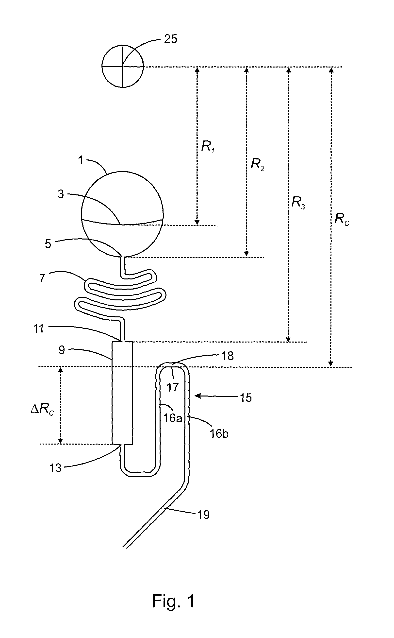
[0025]The hydrodynamic resistance element controls the rate of fluid flow out of the fluid reservoir into the siphoned chamber. The hydrodynamic resistance element provides a hydrodynamic resistance to impede the flow of fluid without actually stopping the flow. A properly designed hydrodynamic resistance element can replace a valve structure for controlling fluid flow, thereby mitigating against the problems of wettability and high pressure associated with the use of valves. The hydrodynamic resistance element has a geometry that is designed to provide the desired hydrodynamic resistance. The hydrodynamic resistance element should be designed with a view to the amount of time (Δt) that the fluid is to be queued in the siphoned chamber before being delivered into the microfluidic circuit. Such design involves various parameters including: the volume of fluid to be released to the microfluidic circuit and which may be initially added to the reservoir; the positions of the fluid level, reservoir outlet, siphoned chamber inlet and siphon crest point with respect to rotation center of the device; the cross-sectional area of the reservoir; the cross-sectional area of the hydrodynamic resistance element; the density of the liquid; and, the angular velocity of the microfluidic platform. Preferably, the hydrodynamic resistance element is designed to satisfy the relationship expressed in Eq. 1a:
[0026]Thus, the time (Δt) needed for releasing a volume of fluid (V) into the microfluidic circuit from the siphoned chamber can be obtained by combining Eq. 1a with Eq. 2 to give Eq. 3:
[0027]It should be noted that while serpentine channels and other curved channels are known in the art, none are designed to provide a hydrodynamic resistance. The intended use of such channels in the prior art is different and the shapes of such channels arise in applications where a longer path for diffusive mixing of species is desired.
[0028]The hydrodynamic resistance element used for controlling the flow rate presents several advantages over simple straight and rectangular microfluidic constrictions. First, due to several limitations

Problems solved by technology

There are however several difficulties with these elements and as for the capillary valves the most important are:The burst frequencies of capillaries depends hyperbolically on their distance from the rotation center.
This can be a serious drawback if different liquids, released at different frequencies by different capillary valves, have to flow through the same region of a microfluidic circuit.
This is a serious limitation for most applications since very few materials used in fabrication of microfluidic devices meet such criteria for aqueous solutions.Often, microbiological protocols require the control of more than two liquids on the same microfluidic platform.
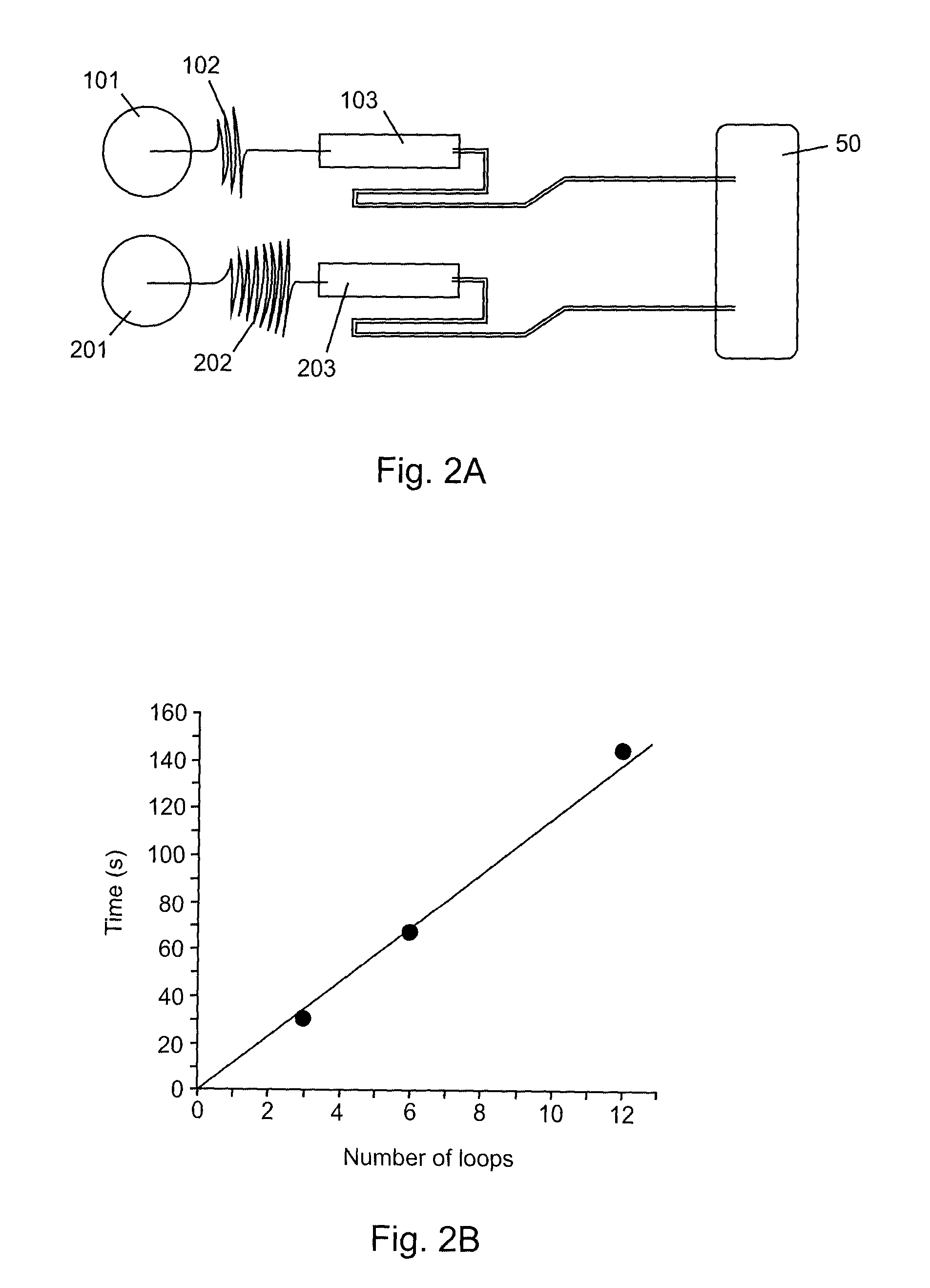
As the number of crests to overcome increases, the necessary time for the liquid to prime a crest increases, needlessly lengthening the biological protocol.As the number of loops in the valve increases, the necessary footprint gets larger accordingly (Siegrist 2009).
This is a serious difficulty since siphon val

Method used


Image

  • Centrifugal microfluidic platform
  • Centrifugal microfluidic platform
  • Centrifugal microfluidic platform

Examples


Embodiment Construction

[0042]Referring to FIG. 1, a temporization and metering circuit in accordance with the present invention is depicted that may be used in a centrifugal microfluidic device. The temporization and metering circuit comprises a hydrodynamic resistance element in the form of serpentine channel 7 in fluid communication via chamber inlet 11 with a siphoned chamber in the form of metering and delay chamber 9 in fluid communication via chamber outlet 13 with siphon 15. The rate of fluid flow from fluid reservoir 1 at reservoir outlet 5 is controlled by the hydrodynamic resistance provided by serpentine channel 7. Since the serpentine channel drains directly into metering and delay chamber 9, the filling time of chamber 9 is also well controlled by the geometry of the serpentine channel. As the level of the fluid in chamber 9 reaches siphon crest 17, the fluid is drained entirely from chamber 9 through siphon 15 into a microfluidic circuit (not shown) in fluid communication with siphon outlet ...


PUM

PropertyMeasurementUnit
Lengthaaaaaaaaaa
Centrifugal forceaaaaaaaaaa
Flow rateaaaaaaaaaa

Abstract

A centrifugal microfluidic device is provided having a microfluidic circuit, a fluid reservoir for providing fluid in the microfluidic circuit, a hydrodynamic resistance element in fluid communication with the reservoir for controlling rate of flow of a fluid out of the reservoir, and a siphoned chamber in fluid communication with the hydrodynamic resistance element and the microfluidic circuit for receiving fluid from the hydrodynamic resistance element and for delaying and metering of the fluid into the microfluidic circuit. The microfluidic device is useful for performing a biological assay. Operation of the device is completely independent on the liquid-solid contact angle and wetting properties of the liquids on the solid material of the platform, and the device does not need a carefully controlled rotation protocol.

Description

CROSS-REFERENCE TO RELATED APPLICATIONS[0001]This application claims the benefit of U.S. Provisional Patent Application Ser. No. 61 / 504,273 filed Jul. 4, 2011, the entire contents of which is herein incorporated by reference.FIELD OF THE INVENTION[0002]The present invention is related to microfluidic devices and their use in performing biological assays.BACKGROUND OF THE INVENTION[0003]Centrifugal (rotating) microfluidic devices have been gaining in importance since they can provide precise control and manipulation of very small amounts of liquids, for example a few microliters only (Jia 2004; Zoval 2004; Madou 2006; Ducree 2007). Recently, several applications of centrifugal microfluidic platforms like staining assays (Chen 2010), whole-cell sensing (Date 2010), real-time PCR (Jia 2004; Focke 2010) and single-molecule detection (Melin 2005) have been demonstrated. In actual (traditional) devices, temporal and spatial control of liquids are achieved by controlling in-plane structure...

Claims


Application Information

Patent Timeline
IPC IPC(8): C12Q1/68
CPCC12Q1/686G01N35/00009B01L3/502746B01L2200/0605B01L2300/0803B01L2300/0867B01L2300/0883B01L2400/0406B01L2400/0409B01L2400/084
Inventor CLIME, LIVIUMOUNIER, MAXENCEROY, EMMANUELVERES, TEODOR
Owner NAT RES COUNCIL OF CANADA
Why Eureka
Try Eureka