
Systems and methods for x-ray and ultrasound imaging

a technology of ultrasound imaging and x-ray, applied in the field of systems and methods for x-ray and ultrasound imaging, can solve the problems of additional drawbacks in the technique of performing ultrasound examinations of the breast, patient anxiety and concern between examinations, and difficulty in co-registering x-ray image and ultrasound imag

Inactive Publication Date: 2014-05-15
GENERAL ELECTRIC CO
View PDF7 Cites 40 Cited by
  • Summary
  • Abstract
  • Description
  • Claims
  • Application Information

AI Technical Summary

Benefits of technology

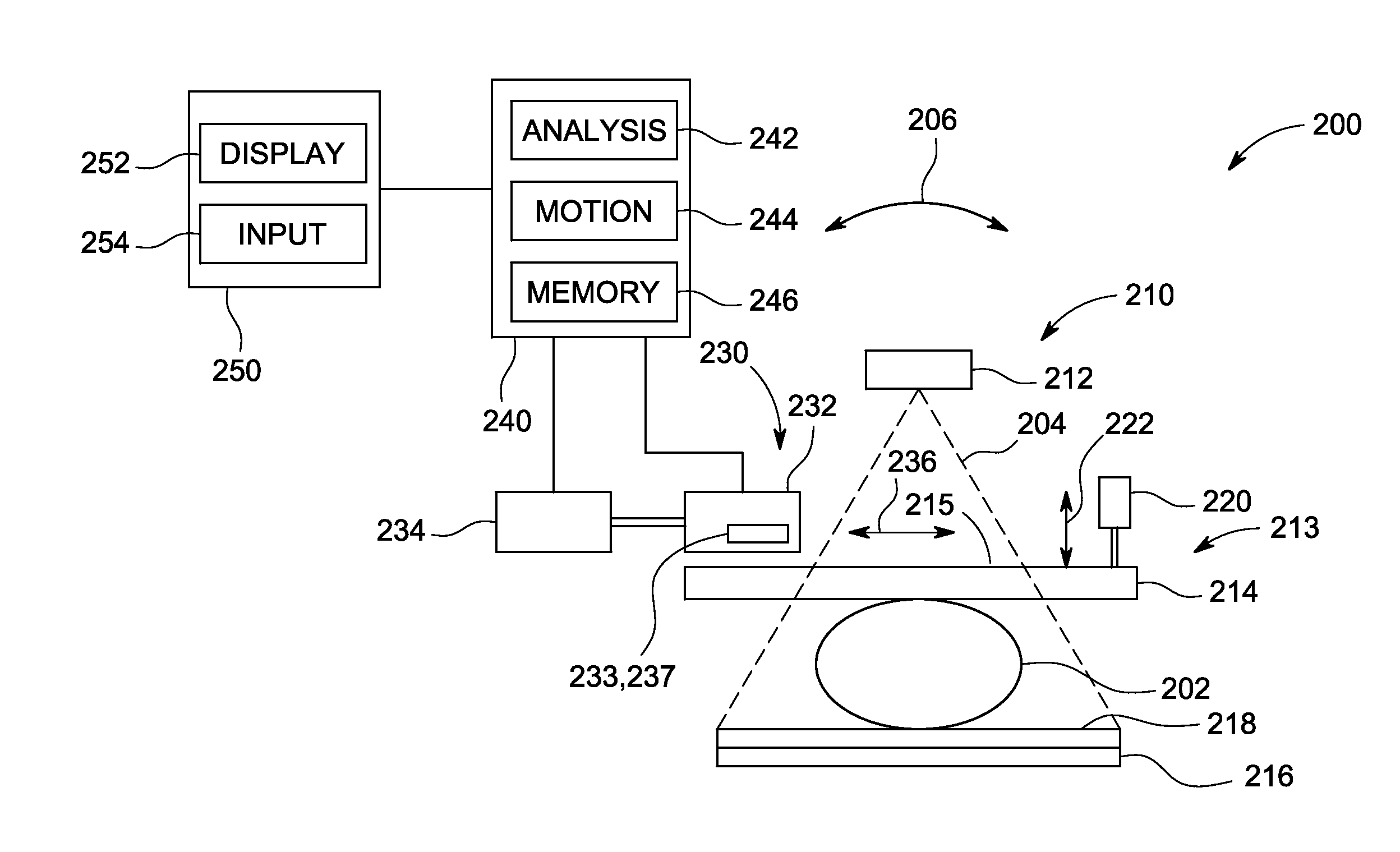
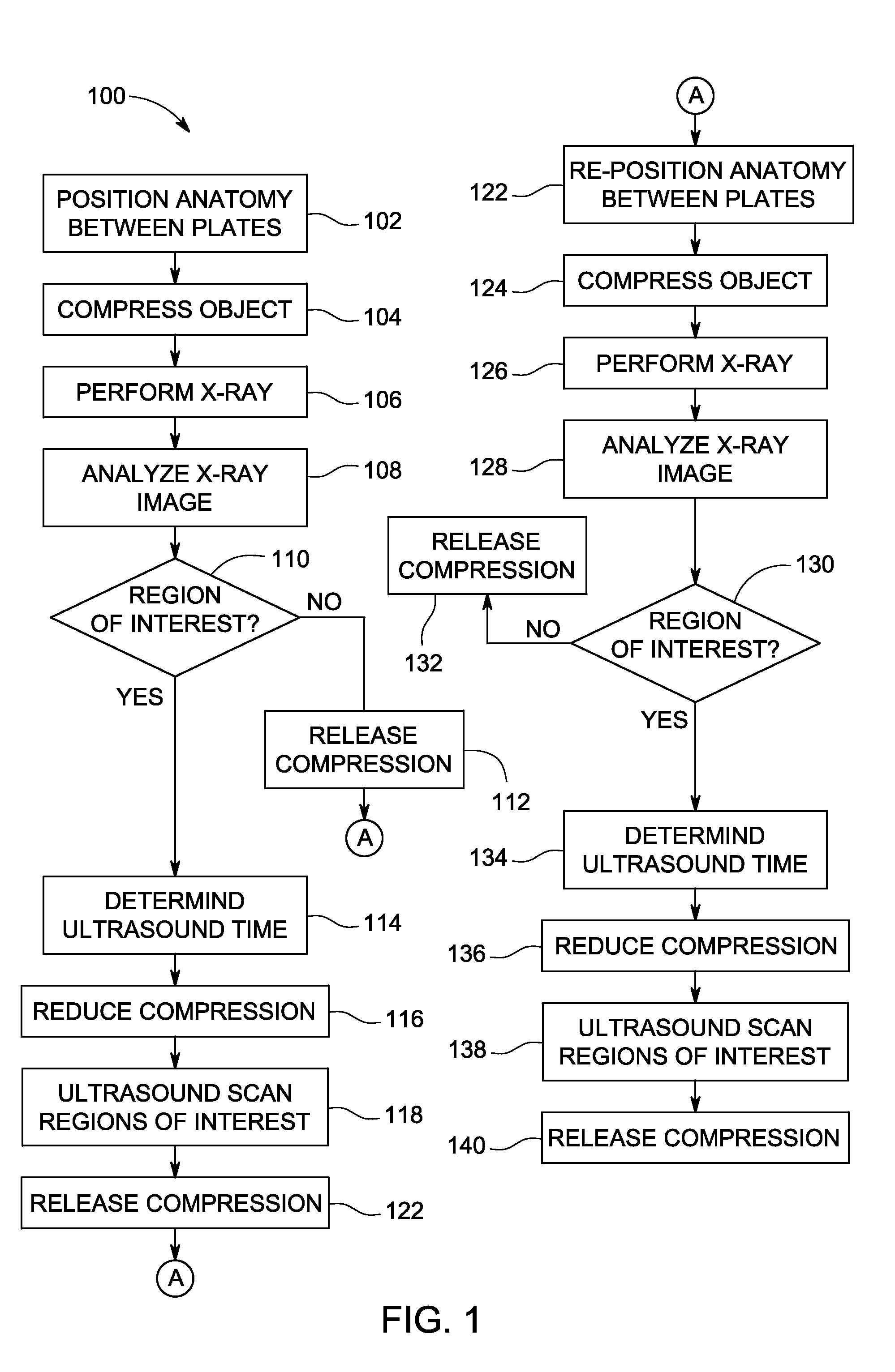
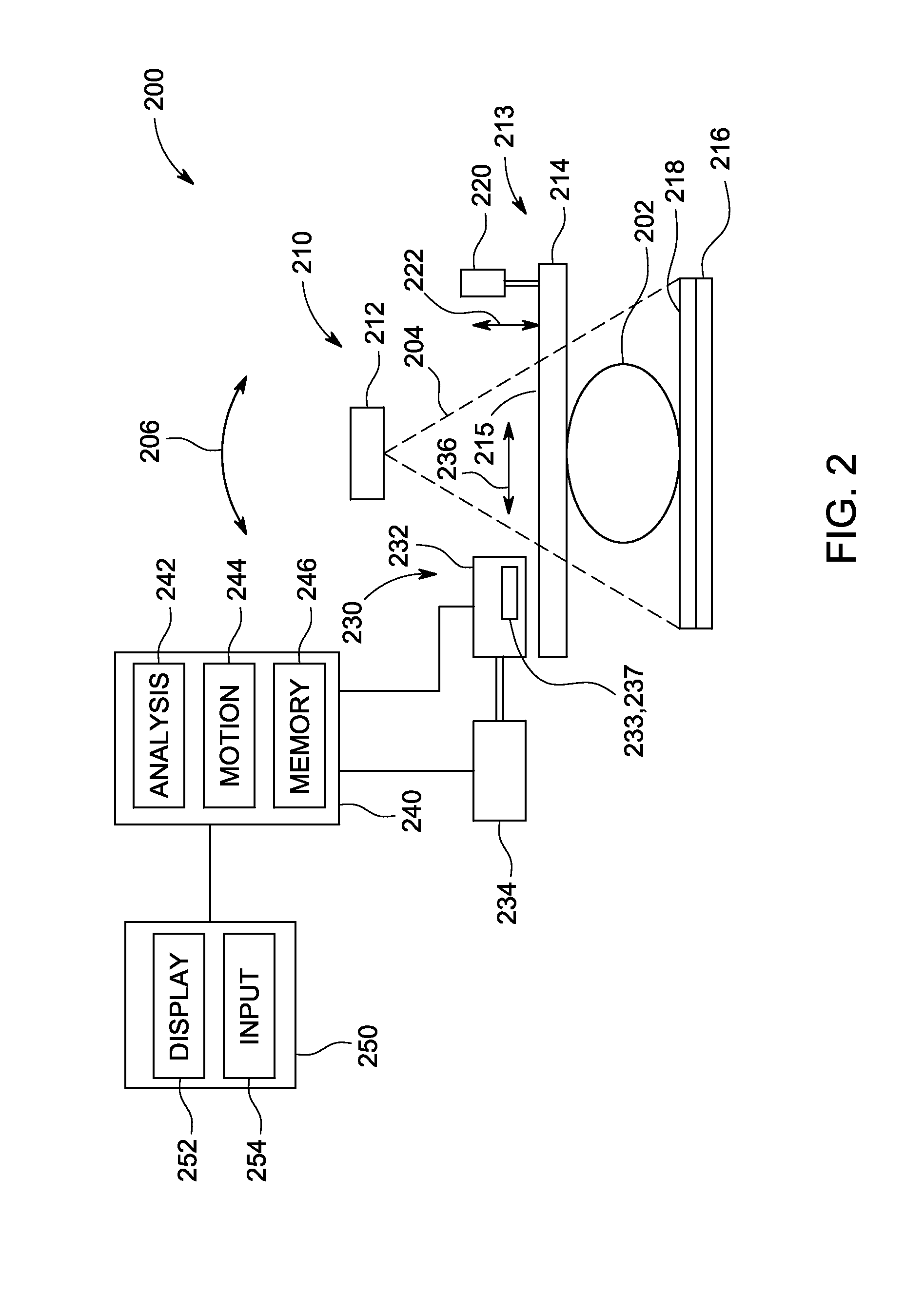
The patent describes an imaging assembly that can obtain an X-ray image and an ultrasound image of an object using a paddle assembly that compresses the object between two plates. The assembly includes an X-ray detection unit and an ultrasound module with an articulable ultrasound transducer for selectively imaging a region of interest while the object remains compressed. The control module positions the ultrasound transducer to scan the selected region while not scanning other parts of the object. The method allows for improved imaging of the object with reduced risk of injury or damage to the surrounding tissues. The computer-readable medium includes software modules for controlling the imaging assembly and obtaining the X-ray and ultrasound images.

Problems solved by technology

Such rescheduling typically involves a delay of days or even weeks between exams.
This amount of time can lead to patient anxiety and concern between the examinations.
Further, because the exams are conducted at separate visits, and also because compression is typically used for mammographic X-ray exams, it is very difficult to co-register the X-ray image and ultrasound image.
Present techniques for performing ultrasound examinations of the breast have additional drawbacks, such as the time associated with such examinations.
For example, previous systems have had high costs associated therewith.
In addition to the cost of the systems, the systems typically involve the time and expense to conduct an ultrasound of the entire breast, as well as patient discomfort during the examination.

Method used


Image

  • Systems and methods for x-ray and ultrasound imaging
  • Systems and methods for x-ray and ultrasound imaging
  • Systems and methods for x-ray and ultrasound imaging

Examples


Embodiment Construction

[0019]Various embodiments will be better understood when read in conjunction with the appended drawings. To the extent that the figures illustrate diagrams of the functional blocks of various embodiments, the functional blocks are not necessarily indicative of the division between hardware circuitry. Thus, for example, one or more of the functional blocks (e.g., processors, controllers or memories) may be implemented in a single piece of hardware (e.g., a general purpose signal processor or random access memory, hard disk, or the like) or multiple pieces of hardware. Similarly, any programs may be stand-alone programs, may be incorporated as subroutines in an operating system, may be functions in an installed software package, and the like. It should be understood that the various embodiments are not limited to the arrangements and instrumentality shown in the drawings.

[0020]As used herein, an element or step recited in the singular and proceeded with the word “a” or “an” should be ...


PUM


Abstract

An imaging assembly is provided including a paddle assembly, an X-ray detection unit, an ultrasound module, and a control module. The paddle assembly includes first and second plates that are articulable with respect to each other and configured to receive and compress an object to be imaged. The X-ray detection unit is mounted proximate to at least one of the first and second plates. The ultrasound module is configured to acquire ultrasound information of the object to be imaged and includes an ultrasound transducer articulably mounted to at least one of the first and second plates. The control module is configured to position the ultrasound transducer to scan a region of interest identified using X-ray information received from the X-ray detection unit, while not scanning at least a portion of the object outside of the region of interest.

Description

BACKGROUND[0001]Various imaging modalities may be used to identify or diagnose medical conditions. For example, mammographic X-ray images may be utilized to identify potential lesions or other abnormalities, such as abnormalities that may be indicative of cancer. Typically, if a potential lesion or other abnormality is identified on a mammographic X-ray image, a follow-up visit is scheduled for an ultrasound exam of the breast to confirm or check the initial diagnosis based on the X-ray image.[0002]Such rescheduling typically involves a delay of days or even weeks between exams. This amount of time can lead to patient anxiety and concern between the examinations. Further, because the exams are conducted at separate visits, and also because compression is typically used for mammographic X-ray exams, it is very difficult to co-register the X-ray image and ultrasound image. Present techniques for performing ultrasound examinations of the breast have additional drawbacks, such as the ti...

Claims


Application Information

Patent Timeline
IPC IPC(8): A61B8/00A61B6/04A61B8/13A61B6/00A61B6/02
CPCA61B8/4416A61B6/02A61B6/04A61B6/4417A61B6/461A61B8/54A61B6/502A61B8/13A61B8/42A61B8/4483A61B6/469A61B6/025A61B6/0414A61B6/5247A61B6/54A61B8/0825A61B8/403A61B8/4209A61B8/5261
Inventor MANAK, JOSEPH JOHNTHOMENIUS, KAIWODNICKI, ROBERTZELAKIEWICZ, SCOTTFAN, YINGSCHMITZ, ANDREAGRIFFIN, WESTON BLAINE
Owner GENERAL ELECTRIC CO
Learn More